If you need to get internet from one building to another across a car park, a river, a plantation, or an entire industrial estate — and you cannot run a cable — the answer is almost always a long distance WiFi link. In Malaysia, a well-engineered point-to-point wireless bridge can reliably carry a full internet connection across hundreds of metres to five kilometres or more, with no monthly line rental to the far site. This guide walks through exactly how these links work, the physics that decides whether yours will succeed, and the step-by-step process professionals follow to build a long range WiFi bridge that survives our tropical rain, heat and lightning.
This is a practical, technical how-to written for facility managers, plantation and estate operators, developers, event organisers and IT teams who keep asking the same question: "how do I connect two buildings wirelessly without trenching a fibre?" By the end you will understand line-of-sight, Fresnel zones, antenna gain, frequency choice, link budgets and lightning protection well enough to plan a link — or to brief a contractor without being sold the wrong thing. If you specifically need to blanket a single large site with coverage rather than link two points, read our companion guide on how to cover a large property with WiFi and internet in Malaysia — the two techniques are often combined.
What Is a Wireless Bridge (And When You Need One)
A wireless bridge is a pair (or more) of purpose-built radios that behave, from the network's point of view, exactly like a long virtual Ethernet cable. You plug one radio into your existing network at the source site, aim it at a second radio at the destination, and the two establish a dedicated wireless link between them. Traffic crosses the air gap transparently: the far building gets the same internet connection, the same subnet if you want it, and the same performance characteristics as if you had buried a cable between them. This is fundamentally different from ordinary WiFi. A normal access point is designed to serve many phones and laptops that wander around a building. A bridge radio is designed to do one thing extremely well — hold a stable, high-throughput link to one specific partner radio far away.
You need a wireless bridge whenever running physical cable is impossible, impractical or absurdly expensive. In Malaysia the classic triggers are: a second building across a road or boundary you do not own; a warehouse, guardhouse or workshop separated from the main office by a yard; a plantation or estate office kilometres from the nearest fibre; a construction or remote industrial site with no telco presence; a jetty, pontoon or island facility across water; or an events site where digging is simply not allowed. Fibre trenching across a public road in Malaysia can require local council permits, wayleave agreements and civil works costing tens of thousands of ringgit and weeks of waiting — a wireless bridge often delivers the same connectivity in a day, at a fraction of the cost, with nothing buried and nothing to dig up later.
The trade is that a wireless link lives and dies by physics you cannot cheat. Cable does not care about trees, rain or the curvature of the earth. Wireless cares about all three. Understanding those constraints is what separates a bridge that runs for years untouched from one that drops out every time it rains. That is what most of this guide is about.
Bridge vs mesh vs repeater — don't confuse them
A consumer "WiFi extender" or mesh node rebroadcasts a nearby signal over tens of metres inside a home. A true wireless bridge uses directional radios and high-gain antennas aimed precisely at each other to carry a link over hundreds of metres to many kilometres. If a salesperson offers you a RM150 "long range extender" to cross 2km of open ground, they are selling you the wrong category of product. Real long-distance links use hardware from enterprise-grade brands engineered for exactly this job.
Point-to-Point vs Point-to-Multipoint
There are two fundamental wireless-bridge topologies, and choosing the right one up front saves money and headaches. The difference is simply how many sites you are linking and how the airtime is shared between them.
Point-to-Point (PtP): One Link, Two Ends
A point-to-point wireless bridge is exactly what it sounds like: two radios, one at each end, dedicated entirely to each other. Both radios use highly directional antennas — often dishes — pointed straight at their partner. Because the entire link and all its airtime is shared between just two devices, PtP gives you the highest possible throughput and the longest possible reach for a given power budget. This is the topology you want when you are connecting two buildings, or feeding one remote site with a big pipe. Modern 5GHz PtP gear can comfortably move several hundred megabits per second over a clean multi-kilometre link, and 60GHz gear can push well over a gigabit over shorter, obstruction-free hops.
Typical PtP hardware includes Ubiquiti's airMAX and airFiber lines (the popular NanoBeam, PowerBeam, LiteBeam and airFiber dishes), Cambium's ePMP Force and PTP series, MikroTik's wAP/LHG/Wireless Wire radios, and TP-Link's Omada/Pharos outdoor CPEs. In practice, a single matched pair of PowerBeam-class dishes is the workhorse of Malaysian long-distance links: they are affordable, well understood, and rugged enough for our climate when installed correctly.
Point-to-Multipoint (PtMP): One Hub, Many Clients
Point-to-multipoint flips the model. Instead of two dedicated radios, you install one central "base station" or "sector" radio with a wide-beam antenna — say 90 or 120 degrees of coverage — and then multiple client radios out at the surrounding sites, each aimed back at the hub. The base station serves them all. This is how a plantation head office might feed six field offices, or how a business park operator might deliver internet to a dozen units from one rooftop, or how a WISP (wireless internet service provider) covers a whole neighbourhood from a tower. The airtime is now shared across every client, so per-site throughput is lower than a dedicated PtP link, but the cost per additional site is far lower — you only add one small client radio per new location, not a whole new pair.
Cambium's ePMP and Ubiquiti's airMAX sector systems (a Rocket radio with a sector antenna, plus LiteBeam/NanoStation clients) are the classic PtMP platforms. Good PtMP gear uses time-division scheduling (TDMA) rather than plain WiFi contention, which is what lets a hub cleanly serve many distant clients without them stepping on each other — a real weakness of using ordinary access points for this job over distance.
Which Topology Should You Choose?
- •Two sites, need maximum speed: choose PtP. A dedicated pair gives the far building the fattest, most stable pipe.
- •Three or more sites radiating from one hub: choose PtMP. Adding clients is cheap and each new site only needs one radio.
- •One critical high-bandwidth site plus several minor ones: often the best answer is a hybrid — a dedicated PtP link to the important site, and a PtMP sector for the rest.
- •Very long single hop (5km+): PtP with dish antennas, almost always. Wide PtMP sectors sacrifice too much gain to reach that far cleanly.
The Physics of Range: Why Distance Is Never the Whole Story
Vendors love to print headline range figures — "up to 15km!" — on the box. Those numbers are achieved in ideal conditions over flat, empty terrain with perfect alignment. Whether YOUR link reaches its target depends on a handful of physical factors that all have to line up. Get one badly wrong and it does not matter how expensive your radios are. Let us go through them in the order that matters.
Line-of-Sight: The First Non-Negotiable
At the frequencies used for wireless bridges (5GHz and above), radio behaves almost like light. It travels in straight lines and does not meaningfully bend around hills or penetrate solid objects. This means you need clear line-of-sight (LOS) between the two antennas: if a person standing at one antenna could see the other antenna, you probably have a link. If a building, a ridge, a stand of oil palms or a water tank sits between them, you do not — the signal is blocked. In flat urban Malaysia the usual obstruction is another building; in estates and rural sites it is almost always trees. This is why nearly every long-distance link involves getting the antennas UP — onto a rooftop, a pole or a mast — high enough to see over whatever is in the way.
A crucial Malaysian caveat: trees are not a fixed obstacle. A link that clears a young rubber or palm canopy today may be blocked in two years as the trees grow. Always survey with tomorrow's canopy in mind, and add mast height accordingly. "It worked when we installed it" is cold comfort when the plantation grows into your Fresnel zone.
The Fresnel Zone: The Invisible Obstacle
Here is where amateurs get caught. Even with perfect visual line-of-sight, a radio link needs clearance in an American-football-shaped zone of space around the direct path called the Fresnel zone. Radio energy does not travel in an infinitely thin line; it spreads into this elliptical volume, and obstacles that intrude into it — even without touching the visual line — cause reflection, diffraction and signal loss. The rule of thumb is that you want at least 60% of the first Fresnel zone clear of obstructions. The zone is fattest at the midpoint of the link, and it grows with distance and with lower frequency.
Concretely: for a 5GHz link spanning 2km, the first Fresnel zone radius at the midpoint is roughly 5.5 metres. That means you want the direct line between antennas to clear any midpoint obstacle by about 3.3 metres (60% of 5.5m), not just barely skim over it. This is the single most common reason a link that "looks fine" underperforms: the installer got visual line-of-sight over the treetops but let the canopy eat half the Fresnel zone at the midpoint, and the link runs at a fraction of its capacity or drops out in rain. When we talk about mast height later, clearing the Fresnel zone — not just seeing the far antenna — is the real target.
Quick Fresnel reality check
For a 5GHz link, the first Fresnel zone radius at midpoint is approximately 5.5m at 2km, 7.7m at 4km, and 8.6m at 5km. You want ~60% of that cleared. So a clean 5km 5GHz hop needs the direct path to clear midpoint obstacles by roughly 5m of vertical space — which, over a maturing palm estate, can mean 15–20m masts at each end. This is exactly the kind of calculation a proper survey produces before anyone buys hardware.
Antenna Gain, Dishes and Beamwidth
An antenna does not create energy; it focuses it. A high-gain directional antenna takes the radio power and concentrates it into a narrow beam, like a torch reflector turning a bare bulb into a spotlight. Gain is measured in dBi, and it is the single biggest lever you have on range. A small panel might be 13–16dBi; a NanoBeam-class dish 19–25dBi; a full airFiber or Cambium dish 28dBi or more. Every 6dB of extra gain roughly doubles the usable range, all else equal. This is why serious long hops use dish antennas at both ends — the narrow, high-gain beam is what lets a modest amount of transmit power reach across kilometres.
The trade-off is beamwidth. A 28dBi dish might have a beam only 4–6 degrees wide. That is fantastic for reach but brutal on alignment: at 5km, a beam a few degrees wide is only tens of metres across at the far end, so the two dishes must be aimed at each other with genuine precision. A dish that is one degree off can lose most of its signal. This is why professional installs never rely on "point it roughly and hope" — they use the radios' built-in signal meters and alignment tones to peak each antenna to its best signal, and lock it down so wind cannot nudge it. Malaysia's bans-and-boundaries note: regulators (MCMC) place limits on maximum transmit power (EIRP) in the licence-exempt bands, and reputable firmware enforces these. High gain is achieved through antennas, not by illegally cranking transmit power.
Frequency Bands: 5GHz, 6GHz and 60GHz
The frequency you use is a fundamental design decision, because it trades range against capacity against interference against weather sensitivity.
| Band | Typical use | Range | Notes for Malaysia |
|---|---|---|---|
| 5GHz | The workhorse for most PtP/PtMP links | Metres to 15km+ | Best all-round choice. Good range, decent capacity, tolerant of rain. Can be congested near towns. |
| 6GHz | Newer bridges where available/licensed | Similar to 5GHz | Cleaner spectrum but availability depends on local regulation — confirm MCMC status before designing around it. |
| 60GHz | Very high capacity, short hops | Up to ~500m–1.5km | Gigabit+ throughput, immune to congestion, but heavily attenuated by rain — risky as a sole link for long Malaysian hops. |
For the vast majority of Malaysian long-distance projects, 5GHz is the right answer: it reaches far enough, carries enough, and shrugs off our rain far better than 60GHz. Reserve 60GHz for short, dense-city hops where you need a gigabit across a street and can accept some weather sensitivity or pair it with a 5GHz backup path.
Rain Fade and the Malaysian Tropics
This is the factor that separates links designed for Europe from links designed for Malaysia. Rain fade is the absorption and scattering of radio energy by raindrops, and it gets dramatically worse at higher frequencies. At 5GHz, even a heavy tropical downpour causes only modest additional loss — a few dB over a long link — which is why 5GHz remains dependable through our monsoon storms. At 60GHz, the same downpour can wipe out the link entirely, because millimetre waves are roughly the size of raindrops and are absorbed heavily. Malaysia gets some of the most intense rainfall rates in the world, and any link designed here must account for it.
The defence against rain fade is link margin — sometimes called fade margin. You engineer the link so that in clear weather it runs with, say, 20dB more signal than the bare minimum it needs. When a storm eats 6–8dB, the link simply drops to a lower speed but stays UP, then recovers when the rain passes. A link built with no margin — barely working on a sunny day — will fall over in the first serious downpour. Designing adequate margin for Malaysian rainfall is a core part of a competent survey, and it is why we always design conservatively rather than to the vendor's optimistic headline distance.
Mast Height and Earth Curvature
Height is the cheapest performance upgrade available. Raising an antenna does three things at once: it clears near-end obstructions like fences and low buildings, it lifts the path above the Fresnel zone over midpoint obstacles like tree canopies, and — over truly long links — it compensates for the curvature of the earth itself. The earth bulges upward by roughly 0.08 metres over a 1km path, but the effect grows with the square of distance: over a 10km link the earth's bulge is about 2 metres at the midpoint. For links up to a few kilometres, earth curvature is minor and it is the trees and buildings that dominate; beyond that, curvature becomes a genuine part of the height calculation.
Practically, in Malaysia the deciding factor is nearly always vegetation. Getting antennas onto an existing rooftop is ideal — it is free height, stable, and easy to power and ground. When there is no tall structure, a purpose-built mast or a hardened pole is used, often 6–20 metres depending on what has to be cleared. Masts must be properly guyed or bracketed, and they must be lightning-safe (more on that below). A common cost-effective pattern is to piggyback on an existing water tank, silo, telco tower structure or building parapet where one is available and permission can be obtained.
How to Do a Line-of-Sight Survey
A survey is where a link is really designed. Skipping it is the number-one cause of failed installations. There are two stages: a desktop study you can do before leaving the office, and a physical verification on site.
Step 1: The Desktop Survey
Start with the two coordinates. Drop pins on the exact rooftop or mast positions for both sites in a mapping tool, and read off the straight-line distance and bearing. Then use a terrain-and-link planning tool — several are free, and vendor tools like Ubiquiti's and Cambium's design planners overlay elevation data — to draw the path profile. This shows you the ground elevation along the route and, crucially, lets you set proposed antenna heights and see whether the direct path and Fresnel zone clear the terrain. The desktop survey answers the big go/no-go questions: roughly how tall do the masts need to be, is there an obvious hill or building in the way, and is the distance realistic for the gear you have in mind. What it CANNOT reliably see is vegetation and recent construction — tree canopies and new buildings rarely show in terrain data — which is why the desktop study is necessary but never sufficient.
Step 2: The Physical Site Survey
On site, the goal is to verify what the map cannot show. The gold-standard technique is a line-of-sight test: get someone to the proposed antenna height at each end — using the actual rooftop, a cherry-picker, a drone, or even a long pole with a bright marker or mirror — and confirm you can visually see the far point over every obstruction. Drones have transformed this: flying a drone up to the planned antenna height and looking back along the path instantly reveals whether a tree line or building blocks it, and at what height it clears. Note the height at which the path opens up — that becomes your minimum mast height, to which you add Fresnel clearance and future tree growth.
The best practice for any important link is a temporary test install: mount the actual radios at the intended heights, power them, align them, and measure the real signal strength and throughput before committing to permanent masts and cabling. A few hours of testing prevents the expensive mistake of erecting a mast only to discover the link is marginal. Record signal level (RSSI), signal-to-noise ratio, and a real throughput test in both directions. If the numbers are strong with comfortable margin, you can build with confidence; if they are marginal, you adjust height, antenna or frequency before pouring concrete.
How to Estimate Achievable Distance
"How far can it go?" is the most common question and the least useful headline number. The honest engineering answer comes from a link budget — but the concept is simpler than it sounds.
The Link Budget in Plain English
A link budget is just a running total of gains and losses along the path, ending with how much signal arrives at the far radio compared to how little it needs. You start with transmit power, add the transmit antenna's gain, subtract the "free-space path loss" (the natural spreading-out of the signal, which grows with distance and frequency), subtract any cable losses, add the receive antenna's gain — and the result is the received signal level. Compare that to the radio's receive sensitivity (the weakest signal it can decode at a given speed) and the difference is your link margin. Positive margin with headroom for rain means a good link.
The two big levers are antenna gain and frequency. Free-space path loss over a 5km 5GHz link is roughly 120dB — a huge number — but a pair of 25dBi dishes puts 50dB of gain back into the equation, and the radios themselves are sensitive enough to work with what remains, with margin to spare. You do not need to hand-calculate this: vendor planning tools and any competent installer will produce a link budget for your specific distance, heights and gear, and tell you the expected signal, margin and throughput before you buy. The point of understanding it is to know what to ask for — "show me the link budget and the fade margin" is the single best question you can put to a contractor.
Real Distance Expectations in Malaysia
Cutting through the marketing, here is what to realistically expect for a well-installed, clean line-of-sight 5GHz link in Malaysian conditions:
- •Up to ~500m: almost trivial. Modest panel antennas, high throughput (hundreds of Mbps), huge margin. This covers most across-the-yard and across-the-road links.
- •500m to ~2km: straightforward with NanoBeam/PowerBeam-class dishes and proper alignment. Reliable multi-hundred-Mbps links with good rain margin.
- •2km to ~5km: very achievable with dish antennas at both ends and adequate mast height for Fresnel clearance. This is the typical "wireless bridge 5km" sweet spot most estate and remote-office links live in.
- •5km to 15km+: genuinely possible with high-gain dishes (airFiber/Cambium PTP class), tall masts and careful design — but every metre demands better line-of-sight, more margin and more precise alignment. This is expert territory.
The distances that fail are almost never the ones that ran out of theoretical range — they are the ones where trees intruded on the Fresnel zone, the antennas were misaligned, or the link was built with no rain margin. Clean line-of-sight and honest margin matter far more than chasing the vendor's maximum-distance figure.
Getting Internet TO the Far Site (Starlink Backhaul)
A wireless bridge moves internet from A to B — but it does not create internet. Sometimes the whole point is to extend an existing connection from a main site out to a building that has none. In that case, the bridge carries the main site's fibre or line out to the far end, and you are done. But increasingly the harder problem is that neither site has a usable line to begin with — a remote plantation office, a construction camp, an island resort, a rural estate — where fibre simply is not available and mobile coverage is patchy.
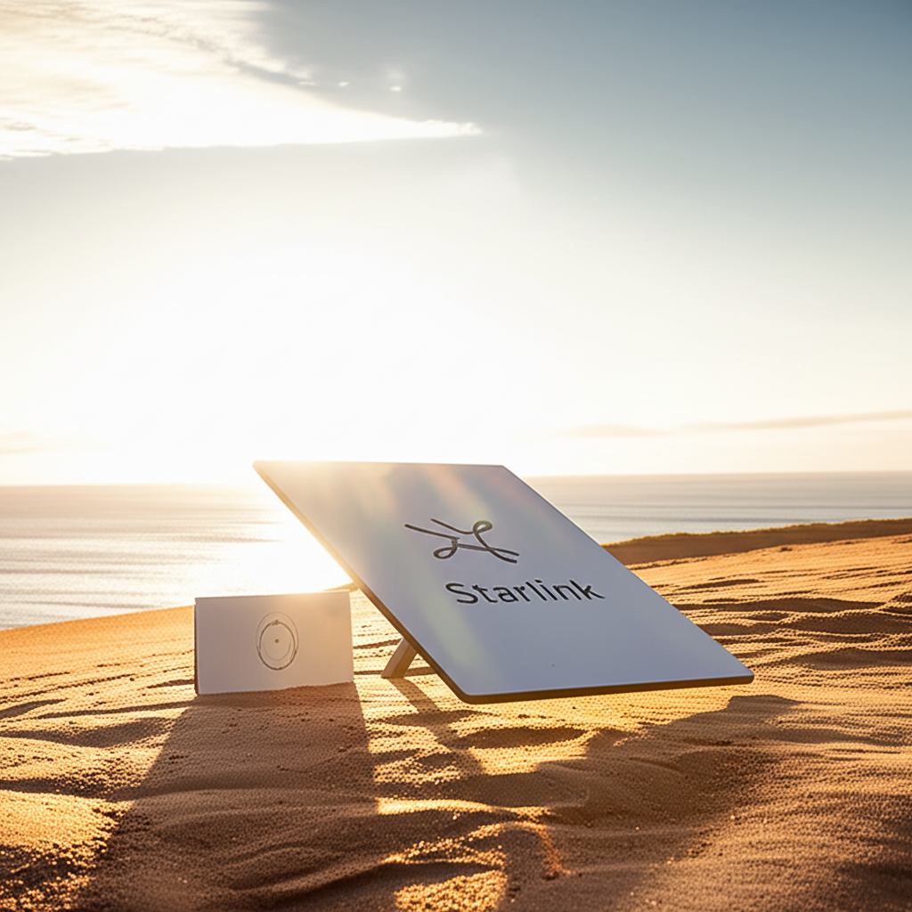
This is where Starlink has changed the game in Malaysia. A Starlink dish delivers a genuine high-speed satellite internet connection almost anywhere with a clear view of the sky — exactly the sort of remote location where wireless bridges are needed. The powerful combination is to put Starlink at whichever site has the best sky view and power, then use a wireless bridge (PtP or PtMP) to distribute that connection to the other buildings on the property. One Starlink can feed an entire remote compound: the main office gets it via Starlink, and the workshop, guardhouse and staff quarters get it via wireless bridges. We cover this remote-first architecture in depth in our complete guide to remote-site and industrial internet in Malaysia — for many rural projects, Starlink backhaul plus wireless distribution is the only architecture that works at all.
Starlink + bridge: the remote-site pattern
Put the Starlink where it has the clearest sky and reliable power. Feed its output into your network at that site. From there, run point-to-point or point-to-multipoint links to every other building. The far buildings need no line of their own — just power and a client radio. Translife offers Starlink rental and deployment precisely for projects like these, so you can pair satellite backhaul with a proper wireless distribution network without buying hardware you only need for one project.
Powering Remote Radios: PoE, Solar and UPS
A bridge radio on a mast a kilometre from the nearest building still needs power, and how you deliver it is a real design question. The universal answer for the radio itself is Power over Ethernet (PoE): the same Ethernet cable that carries data also carries DC power to the radio, so a single outdoor-rated cable runs up the mast. This is elegant because it means only one cable to the radio and no separate power run up a pole. Nearly all bridge radios ship with a PoE injector, and the practical limit is the Ethernet cable length — roughly 100 metres from the injector to the radio, which is why the injector and any power source live at the base of the mast or in the nearest building, not up top.
Where a site has no mains power at all — a mid-path relay on a hilltop, a repeater tower in an estate — the radio can run from a solar panel and battery bank, since a bridge radio draws only a few watts. A modest solar-plus-battery setup can keep a relay radio alive indefinitely off-grid, which is a genuinely powerful capability for Malaysian plantations and remote infrastructure. Even at sites with mains power, a UPS or battery backup on the radios and the injector is strongly recommended: our grid has brownouts and storms cut power exactly when connectivity matters most. A small UPS that keeps the radios, the router and the Starlink alive through a short outage is cheap insurance for a link people depend on.
Grounding and Lightning Protection (Critical in Malaysia)
This section is not optional, and it is where cheap installs come back to bite hardest. Malaysia has among the highest lightning strike densities on earth — the Klang Valley in particular sees enormous numbers of thunderstorm days per year. Any antenna you put on a rooftop or mast is, by definition, a raised metal object exposed to the sky. Get lightning protection wrong and a single storm can destroy not just the radio but everything connected to it — routers, switches, even devices inside the building, because a surge travels down the Ethernet cable straight into your network.
Proper protection is a layered system, and every layer matters:
- •Grounding the mast and radio: the metal structure and the radio's ground point must be bonded to a proper earth electrode with heavy-gauge conductor, giving a strike a low-resistance path straight to ground rather than through your equipment.
- •Ethernet surge protectors (gas-discharge arrestors): an in-line surge protector on the Ethernet cable, itself grounded, clamps the voltage from a nearby strike or induced surge before it reaches the switch or router indoors. This is the single most cost-effective device you can add and it is routinely omitted by cheap installers.
- •Air terminal / lightning rod: for taller masts, a dedicated rod mounted above the antenna gives a direct strike a preferred point to hit, keeping the actual current out of the radio and its cabling.
- •Correct cable routing and drip loops: outdoor-rated shielded cable, weatherproofed connectors, and drip loops so water runs off rather than into the radio's port.
No protection scheme makes a direct lightning strike survivable with certainty, but proper grounding and surge arrestors dramatically reduce damage from the far more common nearby strikes and induced surges that account for the great majority of losses. In Malaysia specifically, treating lightning protection as an afterthought is the fastest way to turn a wireless bridge into an annual replacement bill. It is a defining reason many operators eventually bring in a professional after their first DIY link gets fried.
Common Mistakes That Kill Long-Distance Links
Almost every failed long-distance link comes down to one of a short list of avoidable errors. If you internalise nothing else from this guide, internalise these:
- •Ignoring the Fresnel zone: getting visual line-of-sight but letting trees or buildings clip the Fresnel zone at the midpoint. The link "works" but runs slow and dies in rain.
- •Obstructions — especially future ones: designing for today's tree canopy and being blocked in two years as the plantation matures. Survey with growth in mind.
- •Poor alignment: high-gain dishes have narrow beams; "pointing it roughly" leaves most of the signal on the table. Peak the alignment with the radio's signal meter and lock it against wind.
- •No rain margin: building a link that barely works on a sunny day. The first monsoon storm takes it down. Always design with fade margin for Malaysian rainfall.
- •Cheap or mismatched gear: a RM150 "extender" is not a wireless bridge. Consumer kit lacks the antennas, TDMA scheduling and ruggedisation the job needs.
- •No lightning protection: covered above, and worth repeating — the most expensive mistake of all in Malaysia.
- •Interference and channel congestion: using a crowded 5GHz channel near a town without doing a spectrum scan, so neighbouring links and access points degrade yours. A quick site survey of the RF environment picks a clean channel.
- •Flimsy mounting: a mast that flexes in wind swings a narrow-beam dish off target. Solid, well-guyed mounting is part of link reliability, not an afterthought.
DIY vs Professional Installation
Not every link needs a contractor. A short hop across a yard — under a few hundred metres, clear line-of-sight, both ends on existing rooftops with power — is genuinely a DIY-friendly project for a capable IT person. A matched pair of PowerBeam-class radios, a couple of hours to mount and align them, an Ethernet surge protector on each end, and you have a working link. If that describes your situation and you are comfortable on a rooftop, there is no shame in doing it yourself.
The calculus changes fast as distance, height and stakes grow. The moment you need masts erected, Fresnel calculations over a tree canopy, a proper link budget, serious lightning protection, or the link is business-critical, the risks of DIY compound: a mast that fails in wind, a lightning strike that fries your whole network, a link that runs marginal and drops out during your busiest period, or weeks of frustration chasing a problem a survey would have caught. Professionals also carry the right tools — spectrum analysers, alignment gear, tower-climbing safety equipment, drones for LOS — and, importantly, they carry responsibility: a professionally installed link comes with a warranty and someone to call when it misbehaves. For anything beyond a simple short hop, professional installation usually costs less in total than a DIY attempt that has to be redone.
Step-by-Step Planning Checklist
Here is the sequence a professional follows, condensed into a checklist you can use to plan your own link or to sanity-check a contractor's proposal:
- 1.Define the requirement: which sites, how much bandwidth each needs, how critical uptime is, and whether either site already has internet or you need backhaul (e.g. Starlink).
- 2.Choose the topology: PtP for two sites or one big pipe; PtMP for a hub feeding several; hybrid where appropriate.
- 3.Desktop survey: plot both points, get distance and bearing, draw the terrain path profile, estimate required mast heights.
- 4.Physical LOS survey: verify line-of-sight at the planned heights (drone/pole/rooftop), noting vegetation and future growth; ideally do a temporary test install and measure real signal and throughput.
- 5.Produce a link budget: confirm expected signal, throughput and — critically — fade margin for Malaysian rain.
- 6.Select gear: radios, antenna gain and frequency matched to the distance and capacity, from a reputable brand, sized with margin not to the edge of spec.
- 7.Plan power and mounting: PoE runs, solar/UPS where needed, solid masts or brackets that won't flex.
- 8.Plan lightning protection: mast and radio grounding, Ethernet surge arrestors, air terminals for tall masts. Non-negotiable in Malaysia.
- 9.Install, align, and verify: peak alignment with signal meters, lock against wind, confirm throughput and margin, and document the final figures.
- 10.Monitor and maintain: keep an eye on signal over time (trees grow, connectors weather), and have a support plan for when a storm or fault hits.
When to Bring In a Professional (and How Translife Does It)
Everything above is learnable, and for a short, simple hop you can absolutely do it yourself. But long-distance wireless is one of those disciplines where the difference between a link that runs untouched for years and one that fails every monsoon comes down to survey rigour, correct gear selection, proper mast and lightning work, and precise alignment — exactly the parts that are hardest to get right without experience and the right tools. When the link matters to your operation, bringing in a specialist is usually the cheaper path once you count the cost of a redo.
Translife Group has been delivering connectivity across Malaysia and Singapore since 2005, and our wireless connectivity team runs long-distance links as a turnkey service: survey, design, deploy and support. In practice that means we start with a proper desktop and physical line-of-sight survey — including drone LOS checks and, for important links, a temporary test install to measure real signal before we commit — then produce a link budget with honest rain margin for your specific path. We select the right gear for the job (we work across Ubiquiti UniFi and airMAX, TP-Link Omada, Cambium and MikroTik, and pair links with Starlink backhaul where a remote site has no line of its own), erect and ground the masts to Malaysian lightning standards, and align and document the finished link. Where a project also needs indoor cabling and access points at either end, our network cabling and WiFi installation team handles the whole network as one job rather than leaving you to stitch contractors together.
Because we are turnkey, you get one accountable party from the first survey to ongoing support — so when a storm rolls through or a tree grows into the path, there is someone to call who already knows your link. That is the real value of professional delivery on infrastructure people depend on. If you are weighing which brand of hardware suits your site, our enterprise WiFi equipment brand comparison breaks down the major platforms neutrally, and our remote-site industrial internet guide goes deeper on off-grid and backhaul design.
Frequently Asked Questions
How far can a wireless bridge actually reach in Malaysia?
With clear line-of-sight, a 5GHz link comfortably covers up to about 5km with dish antennas at both ends and adequate mast height — this is the typical sweet spot for estate and remote-office links. Longer hops of 10–15km+ are genuinely possible with high-gain dishes and tall masts, but every extra kilometre demands better line-of-sight, more margin and more precise alignment. The distances that fail are almost always the ones with blocked Fresnel zones or no rain margin, not the ones that ran out of range.
How do I connect two buildings wirelessly if I can't run a cable?
Use a point-to-point wireless bridge: one radio on each building, aimed at the other, plugged into each building's network via a single PoE Ethernet cable. As long as the two antennas have clear line-of-sight (get them onto the rooftops if there are obstructions), the far building gets the same internet as the main one, with no monthly line rental and nothing to trench. For a short clear hop it is a same-day job.
Will heavy Malaysian rain break my wireless link?
A properly designed 5GHz link with adequate fade margin stays up through even heavy tropical downpours — it may momentarily drop to a lower speed but recovers. The links that fail in rain are those built with no margin, or those using 60GHz over a long hop (millimetre waves are absorbed heavily by rain). This is exactly why we design conservatively for Malaysian rainfall rather than to the vendor's optimistic headline distance.
What if neither site has internet to begin with?
Put Starlink at whichever site has the clearest sky and reliable power, then use a wireless bridge to distribute that connection to the other buildings. One Starlink can feed an entire remote compound via point-to-point or point-to-multipoint links — the far buildings need only power and a client radio. This Starlink-plus-bridge pattern is often the only architecture that works for truly remote Malaysian sites.
Bringing It All Together
Getting internet across a long distance in Malaysia without cable is a solved problem — but it is a problem solved by physics and rigour, not by buying the radio with the biggest number on the box. A successful long distance WiFi link starts with the right topology (point-to-point for two sites, point-to-multipoint for a hub feeding many), then lives or dies on clear line-of-sight and a clear Fresnel zone, adequate antenna gain and mast height, the right frequency for the distance, and honest rain and fade margin for our tropical climate. Add solid power, and — this is Malaysia — serious grounding and lightning protection, and you have a link that runs for years.
Where a remote site has no line of its own, Starlink backhaul paired with a wireless bridge turns "there's no internet out here" into a working network across an entire property. Whether you build it yourself for a short hop or bring in a specialist for the harder ones, the checklist is the same: survey properly, produce a link budget, choose gear with margin, mount and ground it right, align it precisely, and monitor it over time. Do those things and distance stops being the enemy it first appears to be.
Need to link two sites — or a whole property — wirelessly?
Translife designs and deploys long-distance point-to-point and point-to-multipoint wireless bridges across Malaysia and Singapore — survey to support, with Starlink backhaul, proper lightning protection and honest rain margin built in. Tell us your two locations and we'll tell you exactly what it takes to connect them.
Request a Wireless Bridge Quote →