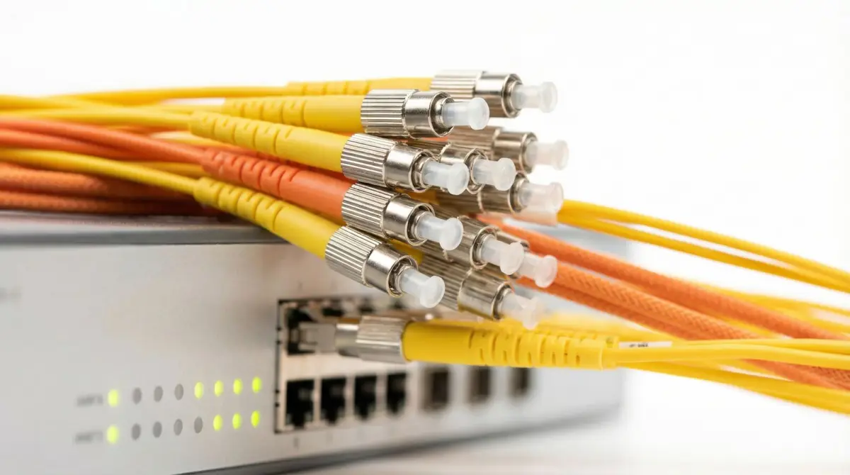
Tested passive network infrastructure
Fibre Optic Cabling
Installation Malaysia
Plan, install, splice, terminate and test building or campus fibre backbones with traceable routes, measured optical loss, labelled cores and practical as-built documentation.
Mon–Fri 9–6 GMT+8 · MY: +60384081397 · SG: +6586605216
Direct answer
A fibre project is complete when every intended core has a known route, termination and test record.
Commercial fibre cabling connects network rooms, floors, buildings, production areas and remote facilities where distance, capacity, electrical environment or future growth justify an optical backbone. The scope should define endpoints, route, fibre and cable construction, core count, connectors, enclosures, equipment interfaces, loss budget, installation constraints and acceptance evidence before work starts. Fibre installation is the passive cable plant; internet service, switches and optical modules are separate dependencies unless the quotation names them.
Technical review
Translife connectivity team
Updated
- Building riser, floor backbone, campus, warehouse and inter-building fibre routes
- New installation, extension, relocation, fault investigation and damaged-link restoration
- Fusion splicing, termination, cleaning, polarity, insertion-loss testing and optional OTDR evidence
- Core schedules, labels, route records, loss results and known exceptions at handover
100+
Languages
10,000+
Clients Served
21+
Years Experience
PM-led
Project-Managed
Selected clients in Malaysia
Search by symptom
The network problems this service addresses
Start with the operational symptom, then measure the radio, cabling and traffic conditions that can produce it.
A building uplink has reached its limit
A floor or remote block may need more capacity or distance than the current copper path supports. Fibre selection still depends on the required interface, route, environment and lifecycle rather than a generic speed claim.
Installed fibre has no test record
Link lights do not document optical loss, polarity, core assignment or spare condition. Baseline results make acceptance, future upgrades and fault isolation more defensible.
Cores, panels and buildings are unlabelled
A working link can become risky when nobody can trace it. Core schedules, both-end labels and panel records reduce accidental disconnection during later moves or restoration.
One fibre cut isolates a remote zone
Spare cores are useful for some failures, while route diversity addresses different physical risks. Two links in one damaged duct do not create an independent path.
A link fails after construction work
Tight bends, pulling stress, contaminated connectors, damaged closures or later building activity can create loss or breaks. Evidence-led testing locates the affected section before replacement is proposed.
The carrier and internal cabling scopes conflict
Provider demarcation, building backbone and customer equipment are different responsibilities. The project records the handoff so passive cabling is not confused with an activated internet service.
Diagram 1
Fibre cable plant from equipment room to remote endpoint
This conceptual path keeps the passive and active components distinct. Exact cable, connectors, modules and loss limits follow the route survey and confirmed equipment interfaces.
- 1
Active equipment
Switch port and compatible optical module define wavelength, connector and link requirements.
- 2
Patch & termination
Clean patch leads and labelled adapters connect equipment to the installed cable plant.
- 3
Fibre route
Suitable indoor, outdoor or protected cable follows the approved pathway and bend limits.
- 4
Splice & enclosure
Fusion splices, trays and closures protect transitions and retain an identifiable core sequence.
- 5
Remote service
The far-end panel and compatible equipment complete the tested floor, building or campus link.
Diagram 2
Optical-link acceptance depends on five evidence layers
A green link indicator proves limited end-to-end operation at that moment. It does not replace route, workmanship, connector, loss and documentation evidence.
Design basis
Required capacity, distance, interfaces, wavelength, fibre type, core count and loss budget.
Physical pathway
Containment, risers, ducts, entries, bend radius, pulling conditions and environmental rating.
Termination quality
Splices, connectors, polarity, cleaning, panels, closures and protected spare management.
Measured performance
Insertion loss and any justified OTDR traces interpreted for the installed link and method.
Operational record
Both-end labels, core schedule, route, results, equipment handoff, exceptions and ownership.
Define the link first
Endpoints, equipment interfaces and responsibility demarcation
Fibre should not be ordered by distance and core count alone; the network service and ownership at both ends determine the usable design.
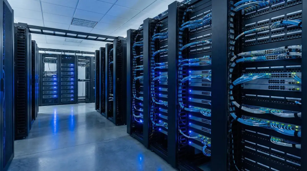
The requirements workshop identifies the buildings, floors, cabinets or equipment that must communicate and the services expected across the link. It records current and planned capacity, interface speed, equipment ownership, distance estimate, available optical modules, connector preference, allowable outage and future expansion. A fibre cable plant can support several generations of active equipment when the physical design is appropriate, but the project does not promise an unspecified future speed. Compatibility is checked against the actual switch and transceiver documentation.
Demarcation matters where a provider enters the premises. The carrier may own the external service and terminate at an agreed handoff, while the property owner controls risers, pathways or an internal backbone. A tenant may own only its equipment and local patching. The scope drawing names each boundary and the party that supplies, configures, powers and supports the components around it. Translife does not represent itself as the internet carrier merely because it installs fibre between internal locations.
A route survey follows the proposed endpoints through telecommunications rooms, risers, ceilings, ducts, outdoor paths or inter-building entries. It records access restrictions, length, existing capacity, fire compartments, moisture, pests, traffic, building works and cable-pulling constraints. Landlord, property, civil, electrical, structural and fire-stopping responsibilities are identified before the route is final. Unknown or inaccessible sections remain survey qualifications rather than being hidden inside a fixed claim.
- Name both endpoints, required services, equipment interfaces and ownership boundaries.
- Separate passive cable installation from provider activation and active network configuration.
- Survey the physical route, access, environment and qualified-trade dependencies.
- State assumptions and inaccessible sections before final quantities are committed.
Match cable to purpose
Single-mode, multimode, indoor, outdoor and core-count decisions
Fibre type and cable construction follow the intended interfaces, length, pathway, environment and replacement difficulty.
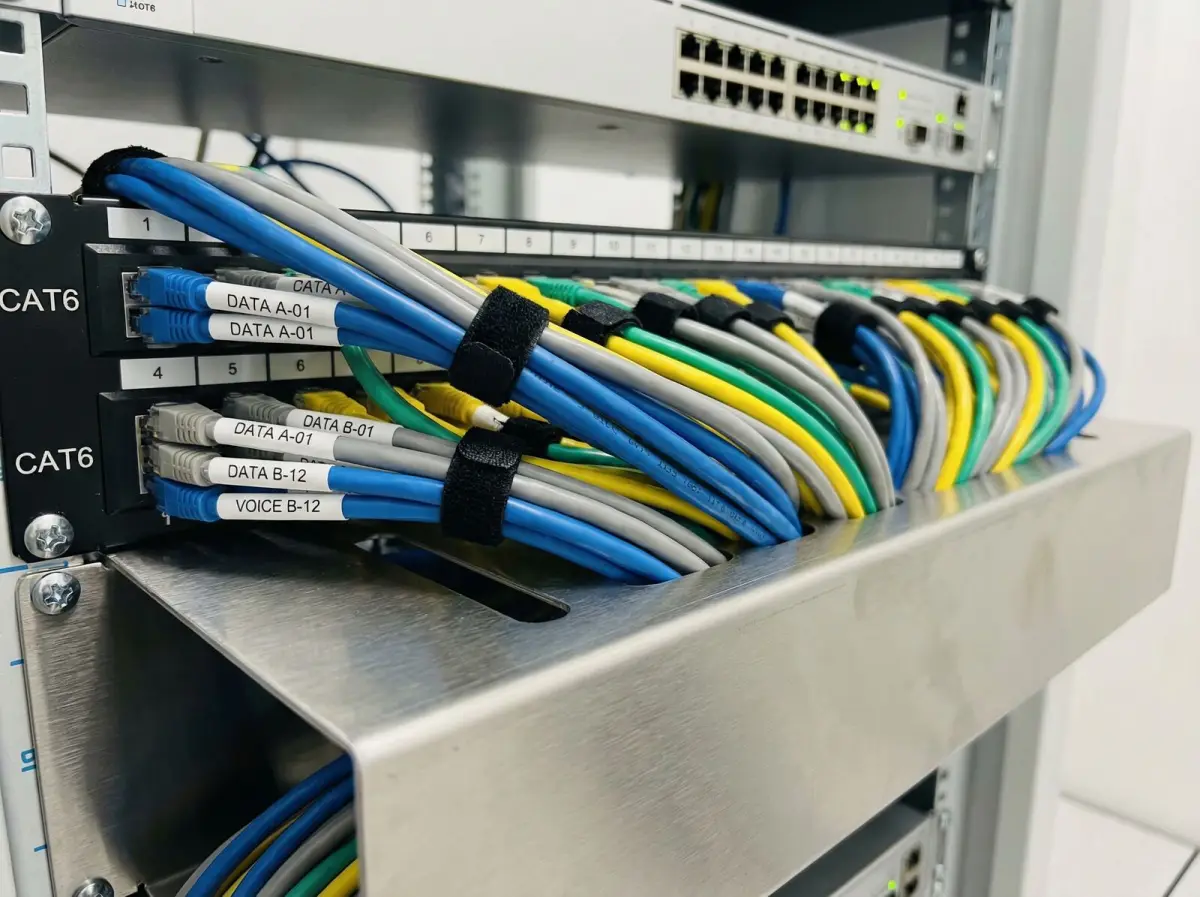
Single-mode and multimode fibre use different optical systems and should be selected with the active interfaces and lifecycle in mind. Single-mode is common for longer links and broad future interface choice, while multimode can serve supported shorter premises links. Neither label alone determines an outcome; transceiver type, wavelength, connector, link budget and vendor support must align. Existing fibre is identified and tested before reuse because jacket colour, a handwritten label or an active link is not sufficient proof of specification.
Cable construction matters as much as the glass. Indoor routes may require cable suited to the building pathway and fire strategy. Outdoor, underground, wet, armoured or direct-burial conditions need an appropriate construction and entry transition. Inter-building links can involve lightning and earth-potential considerations around metallic strength members and connected equipment, so route and cable selection are coordinated with qualified designers where necessary. A generic indoor patch cable is not substituted for a permanent external plant.
Core count balances current circuits, diverse services, spares, growth, panel capacity and repair strategy. More cores can be economical during a difficult route installation, but unused glass still needs documented allocation and protected termination or storage. The schedule distinguishes active, reserved, spare and unavailable cores at both ends. Where true resilience is required, additional cores in one cable are not treated as physical route diversity; the alternate path must address the failure scenario named by the organisation.
Protect the cable plant
Pathways, pulling, bend control, enclosures and building coordination
Installation quality is shaped by the route long before the first connector is cleaned or the first splice is made.
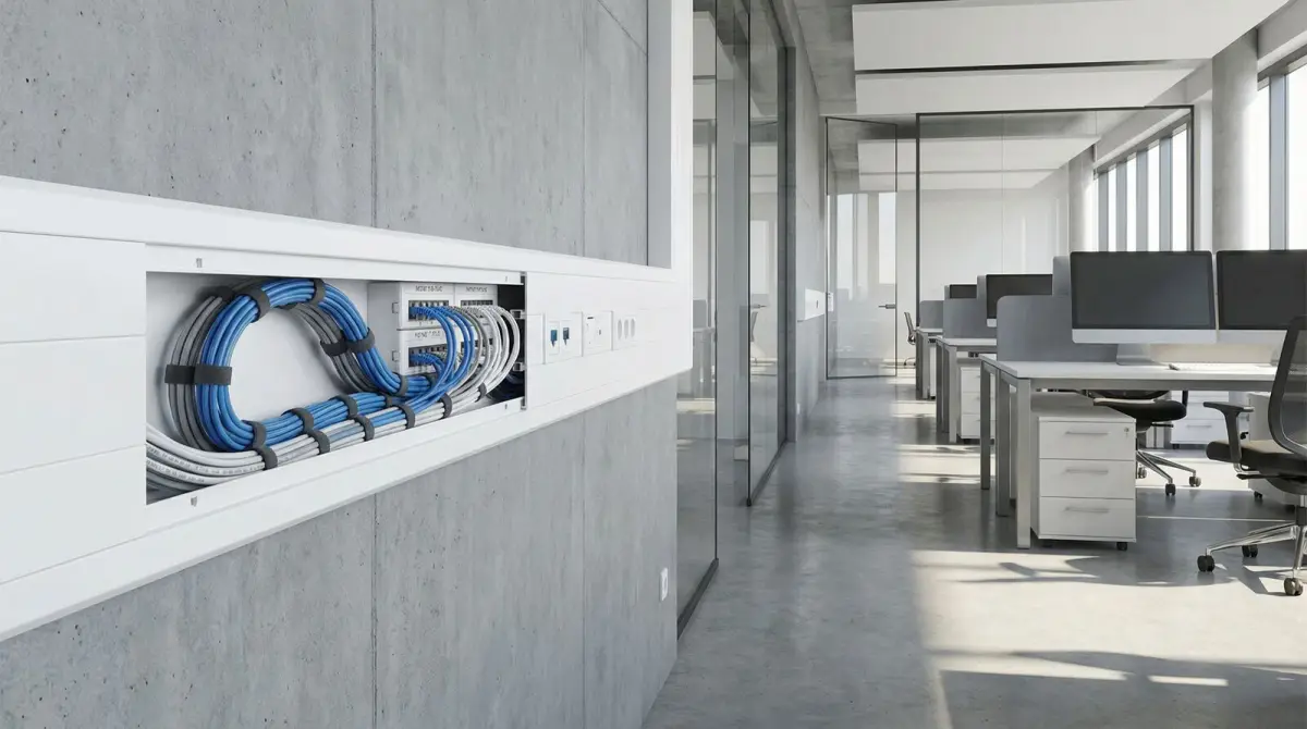
The method statement records drum or reel handling, pulling direction, approved force, bend limits, lubricant compatibility, intermediate access and communication between installers. The cable is protected from sharp edges, crushing, uncontrolled tension and other trades. Service loops are planned at useful locations without creating tight coils or blocking cabinets. Each entry and transition is sealed or protected according to the approved building and environmental requirements, with fire stopping completed by the responsible qualified party.
Riser and ceiling work is coordinated with property access, working-at-height controls, restricted areas and existing live services. Underground or external routes may require civil works, ducts, chambers, warning methods, drainage and reinstatement beyond ordinary cable pulling. The current MTSFB fixed-network technical-code catalogue includes in-building, external and brownfield codes for Malaysian communications infrastructure; applicability and contractual compliance are confirmed by the project’s responsible designers rather than claimed automatically by a marketing page.
Fibre panels, splice closures and trays are placed where they can be accessed, protected and maintained. Cables and buffers enter with suitable strain relief, and splices retain a consistent core sequence. Exposed connectors remain capped and clean. The layout provides patch-cord routing without blocking equipment or creating sharp bends. Photographs can support the record, but labels, core schedules and test identifiers must still correspond to the installed endpoints.
- Use manufacturer limits and an approved method for pulling force and bend control.
- Coordinate riser, ceiling, civil, fire-stopping and restricted-area responsibilities.
- Protect splice trays, panels, service loops, cable entries and future maintenance access.
- Keep labels and core sequence consistent throughout installation and testing.
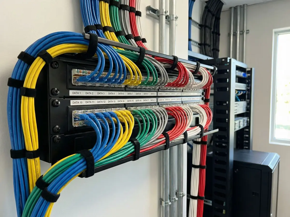
Control every connection
Fusion splicing, connectors, polarity and contamination control
A splice or adapter is a measurable part of the optical path, and clean handling is essential to meaningful results.
Fusion splicing joins prepared fibres and places the protected joint into a managed tray. The team records the cable, tube, core and destination so the physical sequence matches the schedule. Splice-machine estimates can help the installer during work, but they are not a substitute for end-to-end acceptance testing. Mechanical splices or field-installable connectors may suit limited cases when specified, but the chosen method, expected performance and maintenance implications should be stated rather than mixed silently.
Connector type and polish must match the equipment, adapters and patch cords. Mating incompatible polish types or using undocumented adapters can damage interfaces or create excess reflection and loss. Polarity is checked across duplex or multi-fibre paths so transmit and receive reach the intended ports. Panels are labelled at both ends with an identifier that remains meaningful after a switch replacement. Patch leads are sized and routed to avoid unmanaged loops and stress at the connector.
Inspection and cleaning follow an inspect-clean-inspect approach appropriate to the equipment and safety procedure. Dust caps reduce exposure but do not prove a connector is clean. Unnecessary mating and untrained handling can introduce contamination. Fibre work also requires laser-safety and fibre-shard controls appropriate to the system; operators should never look into a fibre end to decide whether it is active. High-power or provider systems require the responsible specialist’s procedure and access control.
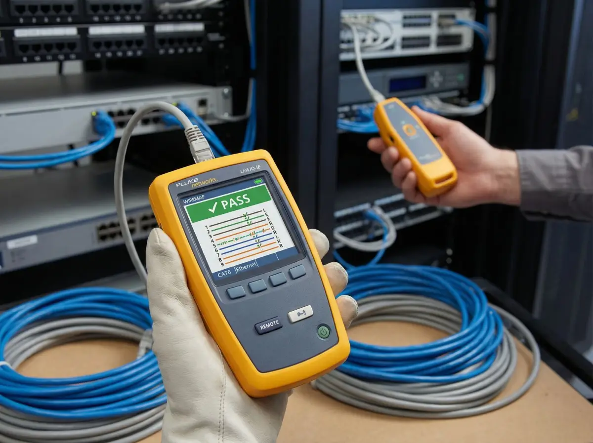
Measure the installed link
Insertion-loss testing, OTDR use and acceptance evidence
The test method should answer a defined question and use references, wavelengths and limits appropriate to the installed link.
Insertion-loss testing with an optical source and power meter measures end-to-end loss using a stated reference method. The wavelengths and launch conditions follow the fibre and intended service. Results are mapped to link identifiers and compared with the agreed loss budget or acceptance limit. The Fiber Optic Association states that installed cable loss is measured with an optical loss test set and that documentation should include insertion-loss data. A simple continuity light or switch reading does not provide the same acceptance evidence.
An optical time-domain reflectometer, or OTDR, can help characterise distance and events, verify installation quality or locate faults when configured and interpreted by trained personnel. FOA cautions that OTDR testing alone should not determine cable loss and can show confusing artefacts on short premises links. The project therefore names whether OTDR traces are required, the direction and launch or receive arrangements, and how they complement rather than replace end-to-end loss measurements.
Testing begins with calibrated or verified equipment, clean reference leads and stable connectors. Failures trigger inspection and fault isolation instead of editing the acceptance limit. Repaired or reterminated cores are retested and their new results retained. The report includes project and link identifiers, endpoints, fibre type, core, wavelength, measured values, method, equipment and date, plus exceptions. Active equipment testing is separate and confirms that the final network service operates after the passive plant is accepted.
- Agree wavelengths, reference method, loss limits and required report format before testing.
- Use insertion loss for end-to-end cable-plant acceptance where applicable.
- Use OTDR evidence for suitable characterisation or fault questions, not as the only loss test.
- Retest changed cores and keep failures, repairs and exceptions traceable.
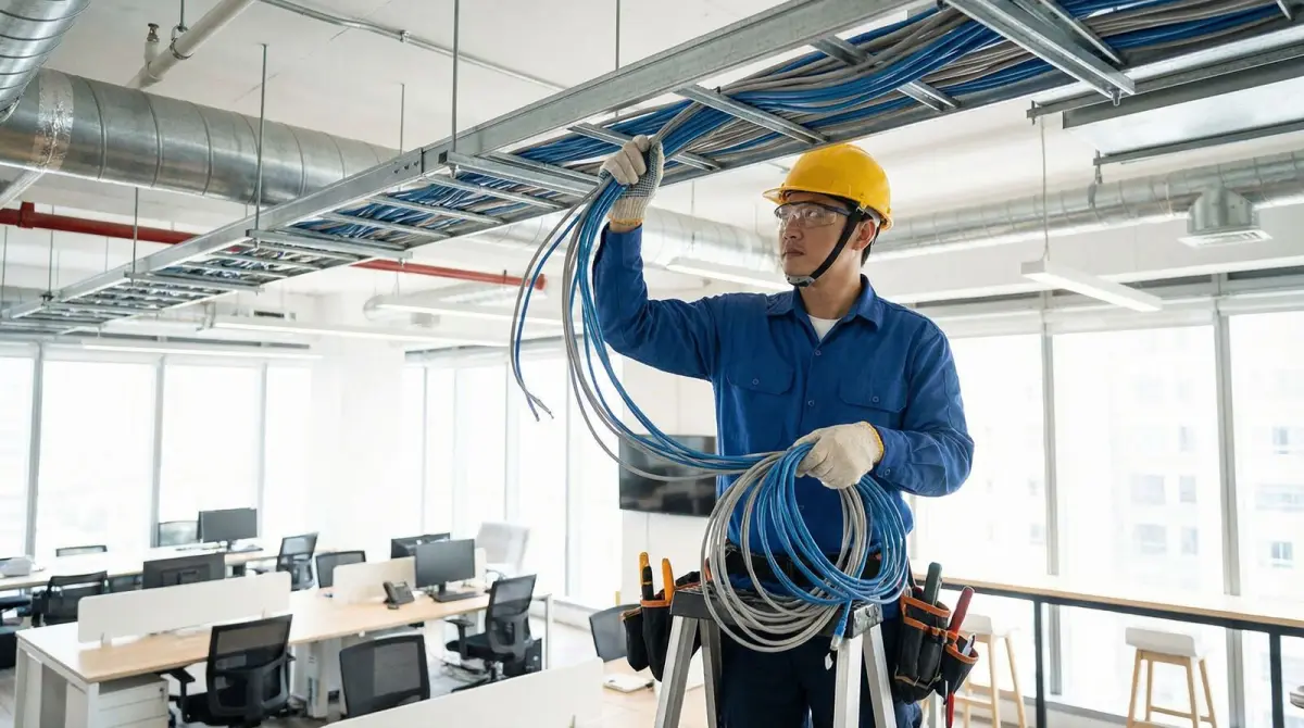
Restore with evidence
Fibre fault investigation, emergency repair and planned migration
Restoration begins by identifying the failure boundary and service impact, then choosing a safe repair or migration that can be validated.
A dark link can result from active equipment, power, patch leads, dirty connectors, reversed polarity, a failed splice or damaged cable. The investigation checks both endpoint devices and the passive path so a cable is not cut or replaced without evidence. Available baseline loss and OTDR records make comparison faster. Where no documentation exists, the team builds a temporary endpoint and core map while protecting live services and unknown fibres from accidental interruption.
A repair plan considers access, damaged length, cable construction, spare cores, enclosure space, restoration priority and the need for a later permanent route. A temporary joint may restore service but should be labelled, protected and recorded as temporary with an owner and replacement condition. If a spare core is used, both-end patching, service assignment and schedules are updated. Emergency work does not remove requirements for safe access, laser control, building permission or specialist civil and electrical coordination.
Planned migration can reduce outage when an old backbone is replaced. New cable, panels and tests are prepared before services move. The cutover schedule lists each circuit, owner, source and destination port, validation action and rollback where practical. A successful optical link is followed by the responsible network or application check. The old plant remains labelled until decommissioning is approved; removal or disposal is outside scope unless explicitly quoted and authorised.
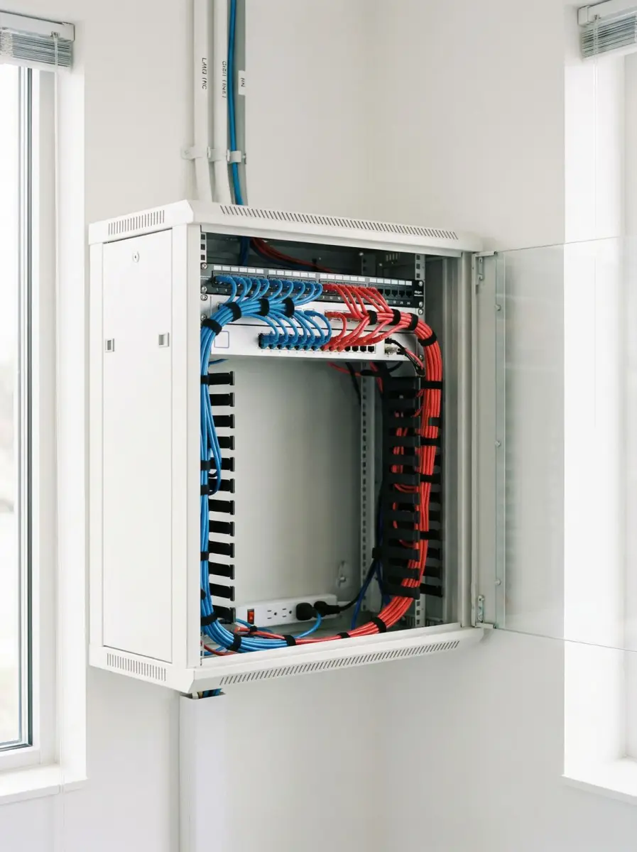
Make the fibre supportable
Core schedules, route drawings, test reports and ownership
Documentation is part of the installed asset because it makes future testing, moves, additions and restoration safer and faster.
The handover record identifies buildings, rooms, panels, cables, tubes, fibres, connectors, splices and active or reserved assignments. A route drawing or marked plan shows significant pathways, entries, closures and access points within the approved disclosure boundary. Both-end labels match the schedule. FOA describes documentation as integral to design, installation and maintenance and recommends recording the path of every fibre, intermediate connections, connector types and loss data.
Test files remain connected to their link identifiers rather than being delivered as an unlabeled instrument export. The organisation receives readable summaries plus agreed native traces where OTDR evidence is included. Photographs show panels, closures and route conditions without exposing unnecessary security-sensitive detail. Known exceptions—such as an inaccessible chamber, unused damaged core or temporary joint—are listed with location, impact and owner instead of disappearing from the completion report.
Handover also records equipment and account boundaries: who owns panels, who controls carrier access, who holds switch or monitoring credentials and who may approve later changes. Spare adapters, patch leads or restoration materials are listed only if supplied. The maintenance plan states whether fibre requires periodic visual inspection, cleaning only when accessed, environmental checks or on-demand fault support. Unnecessary handling is avoided because poorly controlled ‘maintenance’ can itself contaminate or damage a healthy premises link.
- Match both-end labels, core assignments, panels, splices and test identifiers.
- Deliver readable results and agreed native traces with the method and equipment recorded.
- List temporary work, damaged spares, access limits and other exceptions explicitly.
- Transfer property, carrier, network and support ownership at the relevant boundaries.
Decision guide
Choose the fibre scope by link requirement
These categories organise the survey and quotation. Final cable, optics, route and evidence depend on the measured site and confirmed interfaces.
| Link requirement | Questions to answer | Design and evidence focus |
|---|---|---|
| Floor or building backbone | What switches, distances, capacities, risers, rooms and future services must the link support? | Compatible fibre and optics, protected vertical or horizontal route, panels, core schedule and end-to-end loss results. |
| Inter-building or campus link | What external environment, ducts, entries, lightning exposure, civil work and route-failure scenarios apply? | Suitable external plant, qualified pathway coordination, protected terminations, route record and justified resilience design. |
| Existing fibre reuse | Are fibre type, endpoints, connectors, core assignments, condition and previous results known? | Inventory, cleaning, identification, insertion-loss testing, optional OTDR investigation and explicit reuse limitations. |
| Fault repair or restoration | Which services are affected, what baseline exists, where is access available and are spare cores or closures usable? | Endpoint isolation, fault-location evidence, controlled repair, retest, schedule update and temporary-work record. |
| Carrier or tenant handoff | Where do provider, property and tenant ownership begin and end, and who supplies active equipment? | Demarcation drawing, accessible handoff, labelled panels, agreed acceptance boundary and separate provider activation. |
Delivery process
A fibre optic cabling delivery sequence
The sequence connects the intended network service to a protected cable plant and verifiable handover instead of treating cable pulling as the whole project.
- 01
Service and endpoint discovery
Confirm locations, capacity, interfaces, equipment, ownership, outage needs, future use and the passive-versus-active scope boundary.
- 02
Route and environment survey
Inspect rooms, risers, ducts, ceilings, external paths, entries, access, lengths, civil dependencies and building constraints.
- 03
Cable-plant design
Specify fibre and cable construction, cores, panels, connectors, splices, loss budget, labels, test method and acceptance criteria.
- 04
Controlled installation
Coordinate access and trades, protect bend and pull limits, install enclosures, maintain core sequence, splice and terminate cleanly.
- 05
Optical and service validation
Inspect and clean, test insertion loss, capture justified OTDR evidence, correct failures and validate compatible active service separately.
- 06
Documented handover
Transfer routes, labels, core schedules, panels, results, native files, exceptions, demarcation and future support ownership.
Visual field guide
What the physical network work looks like
These illustrative installation views show the components and workmanship discussed on this page; final equipment and routes depend on the survey.
Termination and identifiers
Both-end labels connect physical panels, core schedules and test records.
Protected pathways
Containment, entries and access are planned before pulling begins.
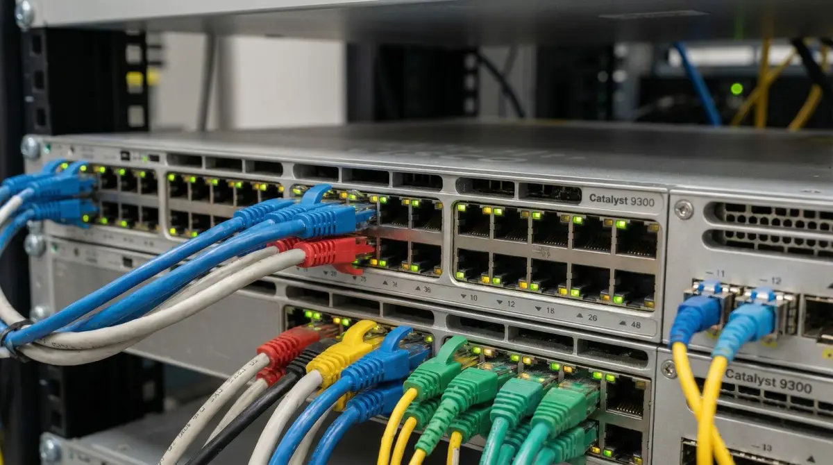
Active equipment boundary
Switch ports and optical modules are checked separately from passive cable acceptance.
Measured acceptance
Test method, wavelength, reference and limits determine what a result proves.
Building and campus distribution
Fibre can connect core, building and floor rooms through named, traceable endpoints.
Maintainable far-end handoff
Panels, patching, power and active equipment remain accessible and owned after handover.
Evidence base
Technical references used for this guide
- Registered Malaysian fixed-network technical codes
Malaysian Technical Standards Forum Berhad
Used to identify the current Malaysian in-building, external and brownfield fixed-network technical-code catalogue, including G024:2024 and G055:2025, without claiming automatic compliance for every project.
- Fibre optic installation reference
The Fiber Optic Association
Used for the design, installation, testing, troubleshooting, documentation and restoration lifecycle and the distinction between insertion-loss and OTDR evidence.
- Fibre optic testing quick-start guide
The Fiber Optic Association
Used for source-and-power-meter testing concepts, appropriate wavelengths, reference methods, measurement limitations and recording results.
FAQ
Questions Malaysian organisations ask before improving WiFi
Straight answers about scope, evidence, disruption and long-term operation.
Should a Malaysian business choose single-mode or multimode fibre?
The choice follows distance, required interfaces, supported optical modules, wavelength, existing plant and lifecycle. Single-mode often suits longer or broadly expandable backbones, while multimode can serve supported shorter premises links. A route and equipment review should decide rather than a generic preference.
How many fibre cores should be installed?
Core count should cover named current circuits, separate services, useful spares, growth, restoration strategy and panel capacity. Extra cores in one cable can help with expansion or a core fault, but they do not create a physically diverse route.
What is included in fibre optic cable testing?
The scope can include identification, continuity and polarity, connector inspection and cleaning, end-to-end insertion loss at agreed wavelengths and optional OTDR traces for suitable characterisation or fault questions. The method, references, limits, equipment and link identifiers should appear in the report.
Is OTDR testing enough to accept a fibre link?
Not by itself. FOA advises that OTDR testing alone should not determine cable loss. End-to-end insertion-loss testing is used for installed loss where applicable, while OTDR evidence can help analyse distance, events, installation quality or faults when properly configured and interpreted.
Can existing unlabelled fibre be reused?
Potentially, after both endpoints, fibre type, connectors, polarity, core assignment and condition are identified and tested. Unknown route or previous damage remains a limitation. Reuse should be based on results and interface compatibility, not only an active link light.
Can Translife install the internet provider’s fibre service?
Translife can scope and install agreed customer or property fibre infrastructure. Provider network construction, service activation, commercial terms and demarcation remain with the licensed provider unless a quotation explicitly states a coordinated provider component.
Can fibre connect two buildings?
Yes where the route, cable construction, entries, distance, interfaces, civil works, environmental and protection requirements support it. Inter-building design also considers pathway ownership, lightning or earth-potential risks, physical damage and whether route diversity is required.
What causes a fibre link to fail after installation?
Possible causes include power or active equipment, dirty or damaged connectors, incorrect patching or polarity, excess bend or stress, failed splices, cable damage, water entry or later construction work. The investigation separates endpoint, connector, splice and route evidence before selecting a repair.
Can a damaged fibre cable be repaired?
Often, depending on damage location, cable construction, access, available length, enclosure capacity and service impact. The repair or spare-core migration should be protected, labelled, retested and added to the core and route records, with temporary work clearly identified.
Does fibre need regular cleaning or maintenance?
Healthy enclosed premises fibre generally should not be opened unnecessarily. Connectors are inspected and cleaned when accessed, while exposed routes, closures or harsh environments may need appropriate inspection. Untrained handling can contaminate or damage an otherwise healthy link.
What documentation should a fibre installer provide?
Handover should include endpoints, route, cable and fibre type, panels, connector and splice details, both-end labels, core assignment, measured loss, agreed native traces, active or spare status, exceptions and property, carrier or support ownership boundaries.
What is needed for a fibre optic cabling quotation?
Useful inputs include endpoint locations, plans, route access, estimated distance, buildings and floors, required capacity, switch and optical interfaces, current fibre records, core needs, outage windows, environmental conditions, civil or landlord constraints and required test evidence.
Explore more
Continue planning your connectivity project
Use the service page that matches the next decision in your network plan.
Testimonials
What Our Clients Say
Trusted by corporations, SMEs, and government agencies in Malaysia and Singapore.
“Great suggestion of the output format of translation which I never thought of. It helps our people at site understand the translation much easier.”
DHL Malaysia
Plan with evidence
Request a fibre cabling assessment
Share the endpoint locations, floor or site plans, route access, buildings and distances, required capacity, current equipment and fibre records, core needs, outage windows, landlord or civil constraints and required test evidence. We will use those inputs to define the survey and installation scope.
Prefer to provide drawings first? Use the contact page and describe the premises, operating hours, known dead zones and approximate user or device count.