
Business WiFi diagnosis in Malaysia
WiFi Site Survey &
Network Upgrade Malaysia
Find out whether weak coverage, congestion, interference, roaming, cabling, switching, configuration or the internet service is limiting your business network—before buying more access points.
Mon–Fri 9–6 GMT+8 · MY: +60384081397 · SG: +6586605216
Direct answer
A WiFi assessment identifies the failing layer before an upgrade is designed.
A professional business WiFi survey does more than look for weak signal. It connects user complaints to evidence from the premises, client devices, radio environment, access points, switches, cabling and internet connection. The output should explain what is wrong, which changes are justified, what can remain, and how the improved network will be checked after work is complete.
Technical review
Translife connectivity team
Updated
- For existing offices, shops, restaurants, hotels, schools, warehouses and commercial premises
- Separates local WiFi faults from internet-line and application problems
- Supports selective improvement instead of automatic full replacement
- Defines acceptance checks around the applications and devices that matter
100+
Languages
10,000+
Clients Served
21+
Years Experience
PM-led
Project-Managed
Selected clients in Malaysia
Search by symptom
The network problems this service addresses
Start with the operational symptom, then measure the radio, cabling and traffic conditions that can produce it.
Dead zones and weak rooms
Calls drop, pages stall or devices fall back to mobile data in particular rooms, corners, floors or outdoor areas. The cause may be distance, walls, mounting position, radio power or an access point that was placed for convenience rather than measured need.
Full bars but slow service
A strong signal icon describes one part of the client-to-access-point link. It does not prove clean airtime, sufficient capacity, a healthy switch uplink, available internet bandwidth or a responsive cloud application.
Peak-hour slowdown
The network seems acceptable when the building is quiet, then becomes difficult during meetings, lunch periods, classes, shift changes or guest check-in. That pattern points toward capacity, contention or upstream limits rather than simple coverage alone.
Sticky or broken roaming
Phones, scanners or laptops remain attached to a distant access point, pause while moving, or reconnect repeatedly. Roaming is a joint behaviour involving coverage overlap, configuration and the client device—not a feature an installer can guarantee for every endpoint.
Unreliable calls and meetings
Voice and video expose jitter, loss and short interruptions that ordinary browsing can hide. Representative active tests help show whether the issue sits in the WLAN, wired LAN, WAN or service being used.
Unknown inherited network
The premises has mixed access points, undocumented passwords, daisy-chained switches or old cable routes and nobody knows what is still needed. An inventory and topology review creates a controlled starting point for change.
Diagram 1
From user complaint to verified improvement
A useful survey follows a traceable sequence. Each stage produces an input for the next, so the recommendation is tied to business requirements rather than a preferred equipment catalogue.
- 1
Define
Record affected users, locations, devices, applications, busy periods and operational constraints.
- 2
Observe
Walk the premises, review plans and inventory the access points, switches, gateways and cable paths.
- 3
Measure
Collect agreed passive or active evidence at representative locations and operating conditions.
- 4
Remediate
Prioritise configuration, relocation, cabling, capacity, equipment and resilience changes.
- 5
Validate
Repeat defined checks after the work and record exceptions, assumptions and follow-up actions.
Diagram 2
Why ‘the WiFi is slow’ has several possible causes
A business WLAN sits on top of physical pathways, switching, gateways and an external service. Diagnosis starts at the symptom but checks every dependent layer instead of treating the access point as the whole network.
Application
Cloud service, video meeting, POS, voice, file transfer or business system response.
Client & radio
Device capability, signal, noise, airtime contention, interference and roaming behaviour.
Access network
Access-point configuration, channel use, PoE availability, switch ports and uplink capacity.
Core & security
VLANs, routing, firewall policy, DHCP, DNS, authentication and traffic controls.
Internet & provider
WAN bandwidth, latency, loss, provider incidents, failover and the destination service.
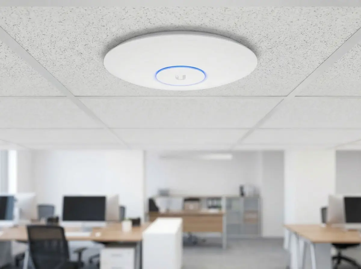
Start with the question
What a business WiFi site survey actually does
The purpose is to turn a vague complaint into a defined technical and operational problem that can be tested.
When staff say that WiFi is bad, they may be describing several different experiences: a laptop will not join, a call breaks up while walking, a room has weak reception, a cloud system pauses at midday, or an internet speed test is lower than expected. Those symptoms do not share one automatic remedy. A survey begins by recording who is affected, where it occurs, what device and application are involved, when it happens, and what acceptable operation looks like. That context prevents a technically tidy upgrade that fails the actual business workflow.
The local wireless network and the internet service are related but separate. A faster fibre plan will not remove a radio shadow behind reinforced walls, while an extra access point will not repair packet loss on the provider link. Likewise, full signal bars do not confirm that a channel has spare airtime or that the switch uplink is healthy. The assessment therefore follows the path from client to access point, through switching and security, out to the WAN and relevant application. The goal is fault isolation, not an attractive heatmap in isolation.
For an existing network, the survey also establishes what is already present. Access-point models, mounting positions, controller status, switch capacity, PoE budgets, cable routes, gateway configuration and network names all affect the options. Some sites need redesign; others benefit from a smaller set of configuration corrections, repaired cable runs or selective replacement. A useful report says which observations support each proposed action and identifies anything that could not be tested during the visit.
- Document the user, device, application, location and time associated with each recurring symptom.
- Check the wired and internet path as well as the radio environment.
- Record limitations such as inaccessible rooms, quiet survey conditions or unavailable credentials.
- Agree how success will be checked before equipment or installation scope is finalised.
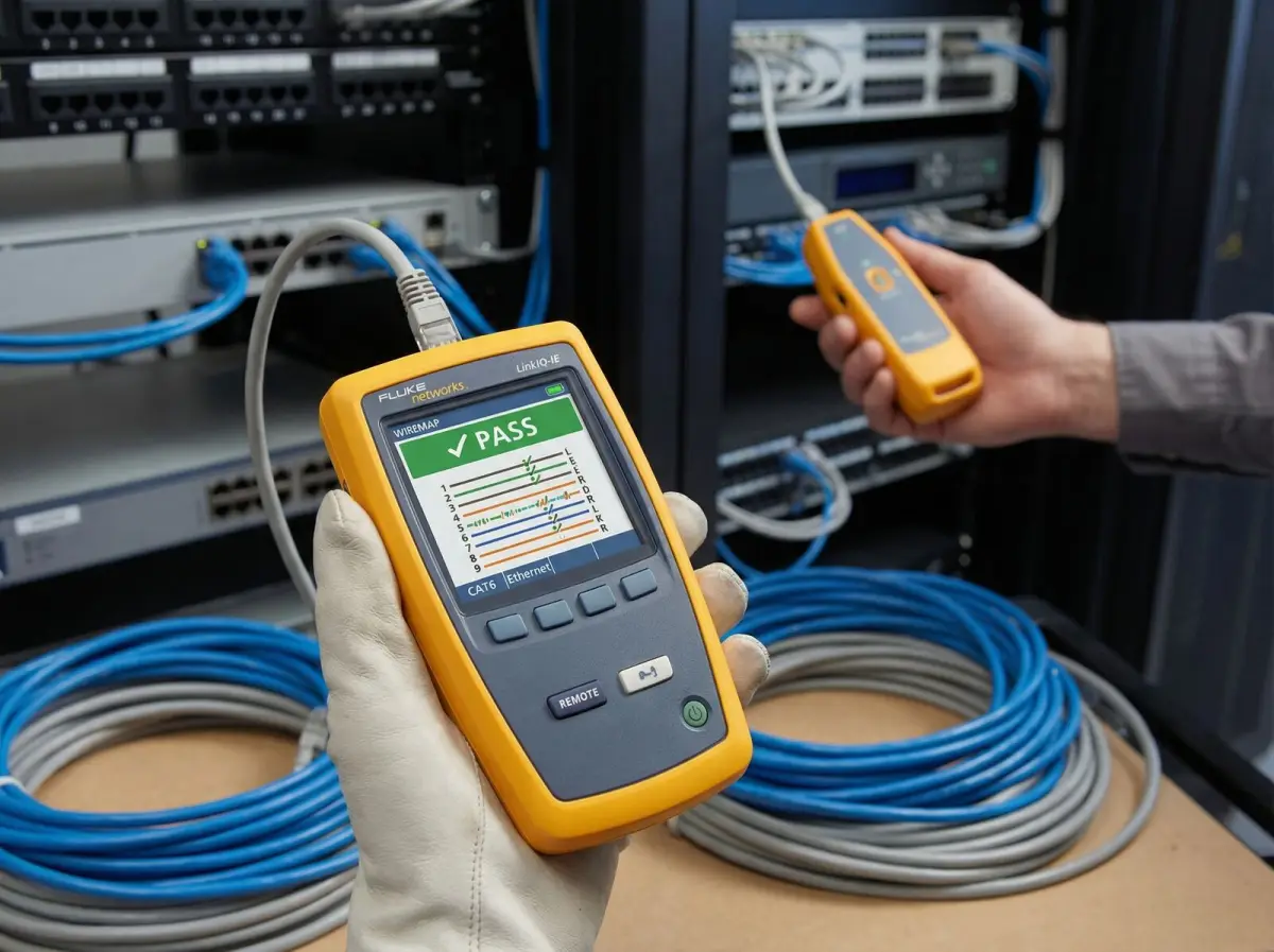
Choose the right evidence
Predictive, passive, active and post-installation surveys
Different survey methods answer different questions, and a proposal should state which methods are included rather than using ‘site survey’ as an undefined label.
A predictive design uses plans, wall assumptions, mounting options and proposed equipment characteristics to estimate coverage and capacity before installation. It is valuable for early budgeting, new premises and comparing layouts. Its limitation is the model: drawings may omit reflective glazing, dense shelving, equipment, ceiling spaces or later renovations. A predictive result is therefore a design hypothesis. It becomes more reliable when the floor plan and materials are accurate, but it should not be marketed as a measurement of a network that has not yet been installed.
A passive survey listens to wireless transmissions without using the surveyed network like a normal client. It can document observed coverage, channel use and surrounding wireless activity across the agreed walk path. An active survey associates to a network and exchanges traffic, allowing the team to observe client-facing behaviour such as throughput, latency or loss under the selected test conditions. Active results depend on the survey adapter, server, traffic method, network load and time, so the report should preserve the test context rather than presenting one number as a universal property of the building.
A post-installation validation checks the finished deployment against the acceptance criteria agreed for that project. This stage matters because actual access-point mounting, cable routes, furniture, inventory and controller configuration can differ from the design. Cisco’s current WLAN survey guidance describes predictive, passive and active approaches and treats validation as evidence for whether the deployed infrastructure meets its requirements. Translife uses that principle without claiming that one universal signal or speed threshold suits every voice, scanner, classroom, guest or office requirement.
Specialised spectrum investigation may be useful where non-WiFi interference is suspected, but it should be explicitly scoped and matched to available equipment. The same applies to temporary access-point placement tests, rooftop or outdoor inspection, after-hours load testing and access above ceilings. Clear inclusions protect the customer from assuming that every possible diagnostic method is part of a basic walkthrough.
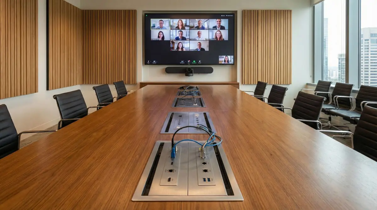
Design for use, not bars
Coverage, capacity and client-device behaviour
A network can cover every room and still perform poorly when too many active clients compete for airtime or when the actual devices hear differently from the survey tool.
Coverage describes whether a usable radio relationship exists in the required area. Capacity describes whether the system can serve the number and type of active devices during real demand. A quiet meeting room may appear well covered during an empty-site walk, then struggle when dozens of participants join video calls. A café may need modest coverage but careful separation between guest browsing and business systems. A warehouse scanner may send little data yet require consistent mobility along a picking route. The design criteria must follow the application, concurrency and operational consequence of interruption.
Client devices are not identical. A current business laptop, an older phone, a handheld scanner and an IoT sensor can have different radios, antennas, power behaviour and supported bands. An access point may hear a device that cannot respond reliably in the other direction. Roaming decisions are also made substantially by the client. The infrastructure can provide sensible cell overlap and compatible features, but it cannot force every endpoint to move at the same moment. Representative devices should therefore be identified early, especially when voice, scanning, POS or managed fleets are involved.
Channel width, transmit power and access-point count interact. Wider channels can offer more peak capacity in suitable conditions but consume more spectrum. Excessive power can make cells larger than intended and encourage clients to stay attached from farther away. Adding access points without a channel and power plan can increase contention instead of relieving it. Improvement work should consider the whole radio plan, available spectrum, neighbouring networks and premises layout rather than equating more hardware with more performance.
- Estimate active concurrent devices, not only the total number registered or owned.
- Identify voice, video, POS, scanner and other interruption-sensitive applications.
- Test representative client types and movement paths where practical.
- Treat channel and power changes as a coordinated plan, followed by validation.
Radio conditions change
Interference, channel use and roaming complaints
The survey should distinguish a weak signal from busy airtime, overlapping cells, outside interference and a client that does not roam as expected.
Business premises rarely operate in an empty radio environment. Neighbouring offices, mall tenants, personal hotspots, wireless cameras and other systems may share or overlap available channels. Some activity is legitimate and unavoidable; the design task is to use the available spectrum deliberately. Measurements taken at one time are a sample, so recurring peak-hour complaints should be correlated with controller history, user reports or observations during a representative busy period where that is operationally possible.
Co-channel use is not the same as a radio shadow. Devices sharing airtime may all show strong reception while waiting longer to transmit. Adjacent-channel or non-WiFi energy can create different symptoms. A basic survey can reveal patterns that justify configuration changes, while difficult intermittent problems may require a separately scoped investigation. The report should be careful about causation: seeing another network does not automatically prove it caused the complaint, and a single speed test does not prove sustainable capacity.
For roaming complaints, the useful test path follows how people or equipment actually move: between meeting rooms, along aisles, across a lobby, between classrooms or through a hotel corridor. The team observes handoff behaviour alongside signal change, latency and application response. Corrective options can include access-point relocation, added coverage, reduced cell size, configuration alignment or client updates. Because the client participates in the decision, the acceptance language should describe tested devices and paths instead of promising seamless roaming for every possible endpoint.
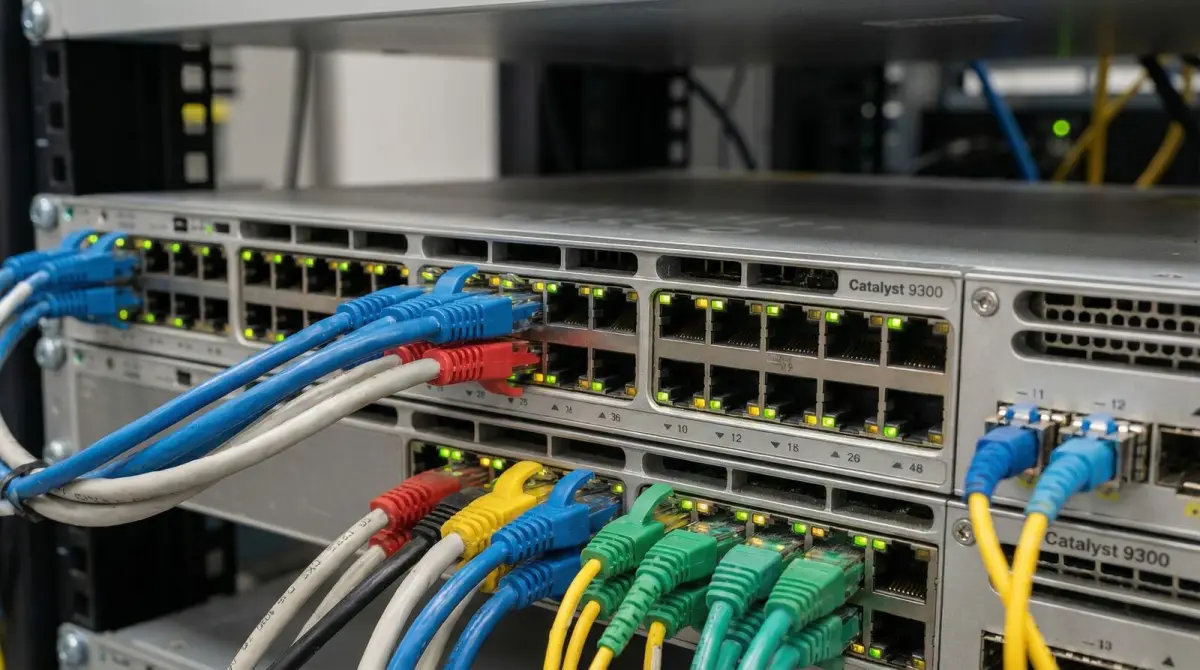
Check below the radio
Cabling, PoE, switching, gateways and internet backhaul
An access point can only deliver what its power, cable, switch, gateway and upstream service allow it to carry.
The wired audit traces access points back to their switch ports and distribution path. It looks for negotiated link rates, errors, unstable ports, undocumented intermediate switches, questionable patching and cable runs that need testing. Power over Ethernet must be considered at both port and switch-budget level, especially when newer access points or additional units are proposed. A visually tidy ceiling installation can still fail if its cable is damaged, its port is constrained or the switch lacks the required power and uplink capacity.
Switch and gateway review focuses on the functions relevant to the reported problem: VLAN availability, port configuration, DHCP and DNS behaviour, routing, firewall policy, controller reachability, traffic controls and WAN health. This does not mean a survey must become a complete cybersecurity audit. It means the design cannot responsibly add wireless capacity while ignoring a bottleneck or fragile dependency immediately upstream. Any inaccessible administrator account or unsupported device should appear as an assumption or risk in the findings.
The internet line is tested as its own component. Advertised package speed, observed throughput, latency and loss are different measures, and results can vary with the test destination and time. If the local WLAN is healthy but the provider path is saturated or unstable, the remedy may involve provider escalation, bandwidth change, application policy or a separately designed backup connection. If the WAN is healthy but one area remains poor, buying a faster package will not solve the radio or cabling problem.
Improve selectively
Upgrade paths that do not begin with replacing everything
The right sequence is to correct low-risk, evidence-backed issues first and replace equipment when capability, condition or lifecycle truly requires it.
Configuration improvements may include a coordinated channel and power plan, consistent security settings, removal of obsolete network names, corrected VLAN mapping or controller cleanup. Physical adjustments can include relocating an access point away from obstructions, changing mounting orientation in accordance with the selected model, repairing its cable or adding a unit where a measured gap or capacity requirement exists. These changes can deliver more value than a fleet replacement when the existing platform is serviceable and manageable.
Selective hardware replacement becomes appropriate when equipment is unsupported, cannot provide required security or management functions, has insufficient radio or uplink capability, fails repeatedly, or creates an inconsistent estate that is expensive to operate. The report should separate immediate remediation from planned lifecycle work. That lets the customer budget a staged programme: stabilise critical areas first, standardise distribution and controller functions next, then address lower-priority coverage or resilience improvements.
Some upgrades reveal dependencies outside the wireless scope. New access points may require new structured cabling, PoE switching, rack space or fibre between floors. A guest service may require properly enforced separation from business systems. A remote wing may be better served by fibre or a designed wireless bridge than by increasing access-point power. Presenting these dependencies early avoids a quote that appears inexpensive but cannot achieve the intended outcome once installation begins.
- Retain equipment that is healthy, supported and suitable for the agreed requirement.
- Separate urgent stability work from planned lifecycle and expansion work.
- Document dependencies such as cable routes, PoE, rack space, controller licences or ISP changes.
- Validate each completed phase against the same operational requirement used to justify it.
Reduce unintended access
Guest, staff, operations and device separation
Improvement is also an opportunity to replace one flat, shared network with access that reflects who and what is connecting.
A small premises often grows from one ISP router and one password. Over time, staff laptops, guests, printers, CCTV, POS terminals, building devices and contractor equipment can accumulate on the same network. That makes troubleshooting difficult and can create unnecessary paths between systems. A redesign can place user and device groups into separately controlled network segments, supported by routing and firewall policy that states which communication is allowed.
Segmentation is not achieved by names or colours in a diagram alone. VLANs or equivalent mechanisms must be carried through switching, wireless configuration, gateway policy and management access, then tested. Guest access commonly needs internet reachability without access to internal systems. Operations devices may need narrowly defined services. Administrator interfaces should not be exposed to ordinary users. The exact controls depend on the premises and selected platform, and they do not automatically make a network compliant with every industry requirement.
Credentials and ownership matter during handover. The customer should know who owns the controller, gateway and cloud accounts; where configuration backups are held; which accounts can make changes; and how former staff or suppliers lose access. An upgrade that performs well but leaves its only administrator account with an installer is not a maintainable outcome. These governance details belong in the project plan alongside coverage and capacity.

Plan around operations
Surveying and upgrading an occupied business
A technically correct plan must also respect working hours, tenant rules, access restrictions, safety procedures and the cost of interruption.
Occupied premises require a staged method. The initial walk records restricted rooms, ceiling access, landlord or mall approvals, noisy-work limits, production areas, guest areas and suitable change windows. Floor plans, asset lists and administrator access can be prepared before the visit. Where a symptom only occurs under load, the team may arrange observation during a busy but controlled period. Where access is unsafe or disruptive, that limitation is recorded and the relevant work is scheduled with the responsible site representative.
Implementation can be divided by floor, zone or dependency. New cabling and switching may be installed in parallel before access points move. Configuration can be prepared and backed up before an approved cutover. Critical services should have a rollback plan proportionate to the change. The project description should avoid promising zero disruption; instead it should identify expected interruptions, who approves them, what is checked before service is returned and how users report unexpected behaviour.
Post-change validation includes both measurements and human workflow. A successful test may check representative rooms, movement paths, device joins, access to permitted services and isolation from prohibited ones. Users should be told what changed, which network to use and where to report issues. Remaining exceptions—such as a room awaiting cable access or an old client that cannot use the chosen security mode—are documented rather than hidden behind a general statement that coverage is complete.
Decision guide
Match the symptom to the evidence and likely remedy
This matrix is a diagnostic starting point, not a remote diagnosis. Similar symptoms can have different causes, so the proposed change should follow observations from the actual network.
| Observed symptom | Evidence to collect | Possible response |
|---|---|---|
| Weak or unavailable service in fixed rooms | Walk-path coverage observations, wall and mounting conditions, client types, access-point positions and uplink status. | Relocate or add an access point, correct mounting or power, repair cabling, or revise the cell plan after confirmation. |
| Strong signal but poor speed | Channel use, active test context, client capability, switch/uplink health, WAN performance and application response. | Reduce contention, correct wired bottlenecks, adjust policy or capacity, or escalate the provider/application path. |
| Dropouts while walking | Representative device, movement route, signal transition, latency/loss and controller/client events where available. | Improve overlap and cell sizing, align configuration, update affected clients or document device-specific limits. |
| Only fails during busy periods | Concurrent clients, airtime utilisation, traffic mix, WAN utilisation and switch/gateway load at representative time. | Add or rebalance capacity, prioritise business traffic, adjust channel plan, or increase the constrained upstream resource. |
| One device class cannot connect | Security compatibility, supported bands, DHCP/DNS behaviour, driver or firmware state and comparison device. | Correct compatibility or policy, update the managed device, or provide a deliberately isolated legacy path if justified. |
Delivery process
A practical survey-to-upgrade engagement
The exact depth depends on site size and problem complexity, but the commercial scope should make these stages and deliverables visible.
- 01
Discovery call and evidence request
Confirm the premises, reported problems, critical applications, representative devices, operating hours, plans, administrator access and known constraints.
- 02
Site walkthrough and inventory
Inspect relevant areas and record access points, switches, gateways, cabinets, cable paths, power dependencies, floor materials and restricted zones.
- 03
Agreed measurements and tests
Collect passive or active evidence appropriate to the question, with test locations, devices, load conditions and limitations preserved in the findings.
- 04
Prioritised remediation design
Separate configuration, relocation, repair, cabling, capacity, security, resilience and lifecycle actions into a sequenced plan with assumptions.
- 05
Controlled implementation
Back up relevant configuration, prepare dependencies, execute approved phases, record changes and use rollback planning for business-critical cutovers.
- 06
Validation and handover
Repeat the agreed checks, document remaining exceptions, transfer account ownership and provide the updated topology, labels or operating notes included in scope.
Visual field guide
What the physical network work looks like
These illustrative installation views show the components and workmanship discussed on this page; final equipment and routes depend on the survey.

Existing infrastructure review
Cable routes and distribution points affect where access points can be positioned and powered.
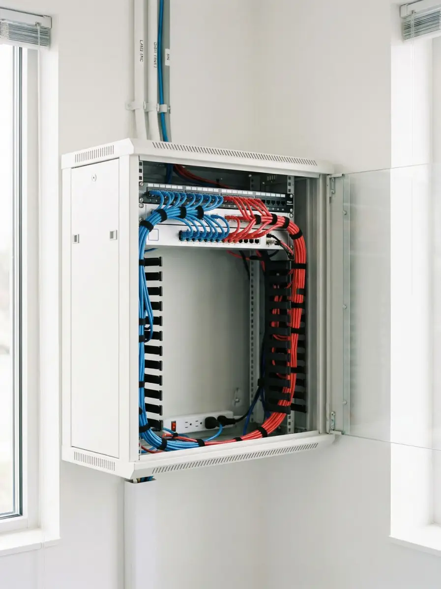
Cabinet and switch audit
Port capacity, PoE, uplinks, labels and account ownership form part of a maintainable upgrade.
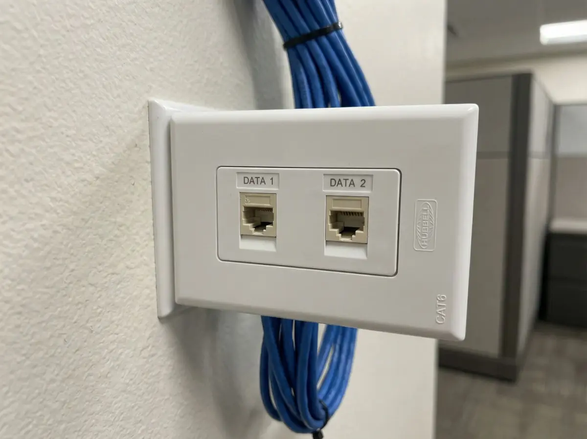
Wired endpoint check
Fixed workstations and critical devices can use wired connections where that is the more dependable design.
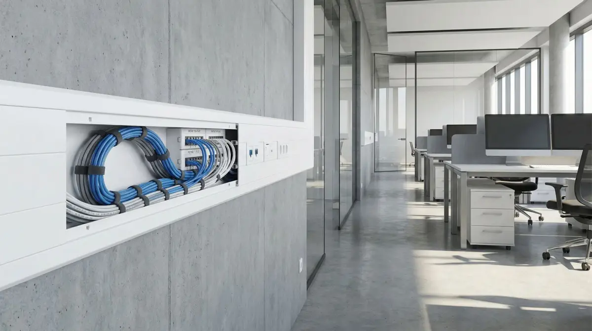
Practical cable routes
The survey considers containment, access, finish, landlord constraints and future serviceability.
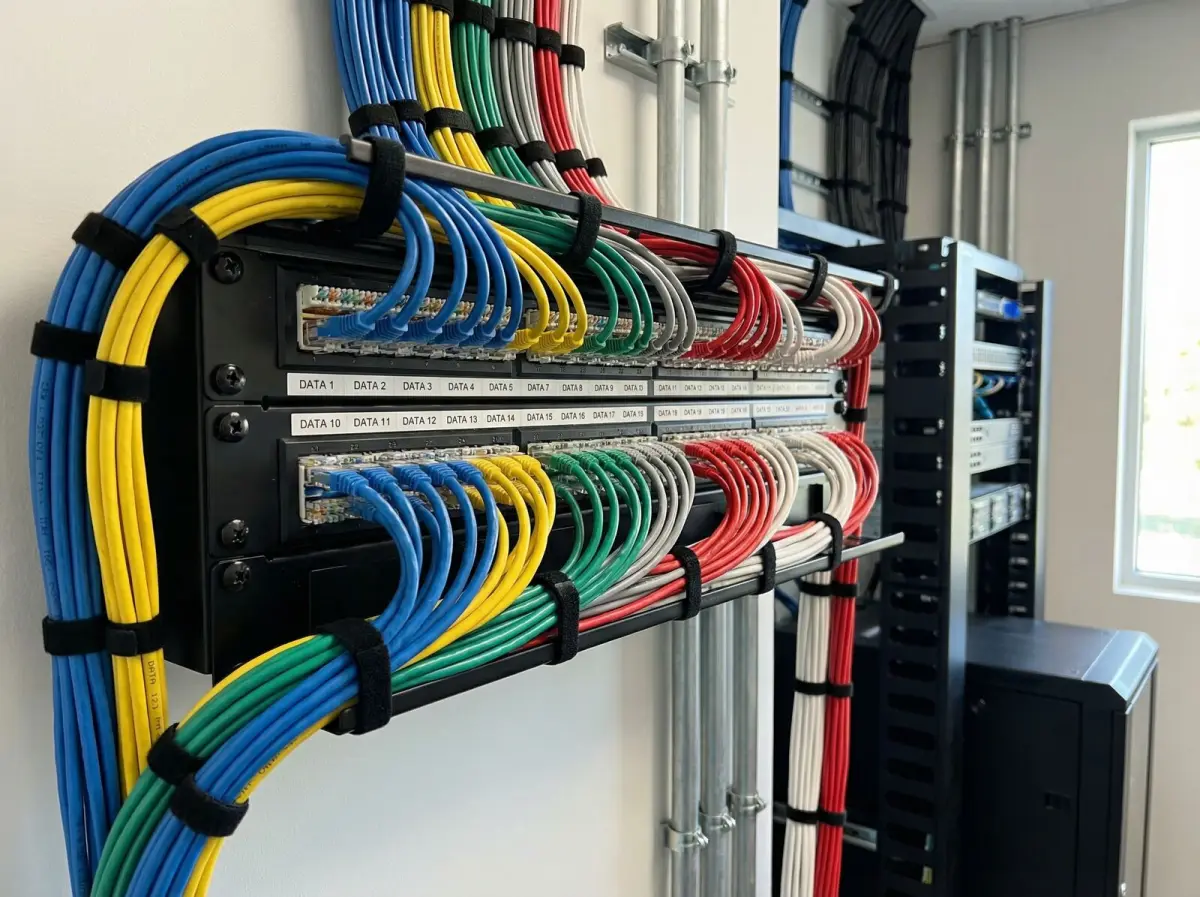
Documented termination
Clear labels and port records reduce ambiguity during troubleshooting and later expansion.
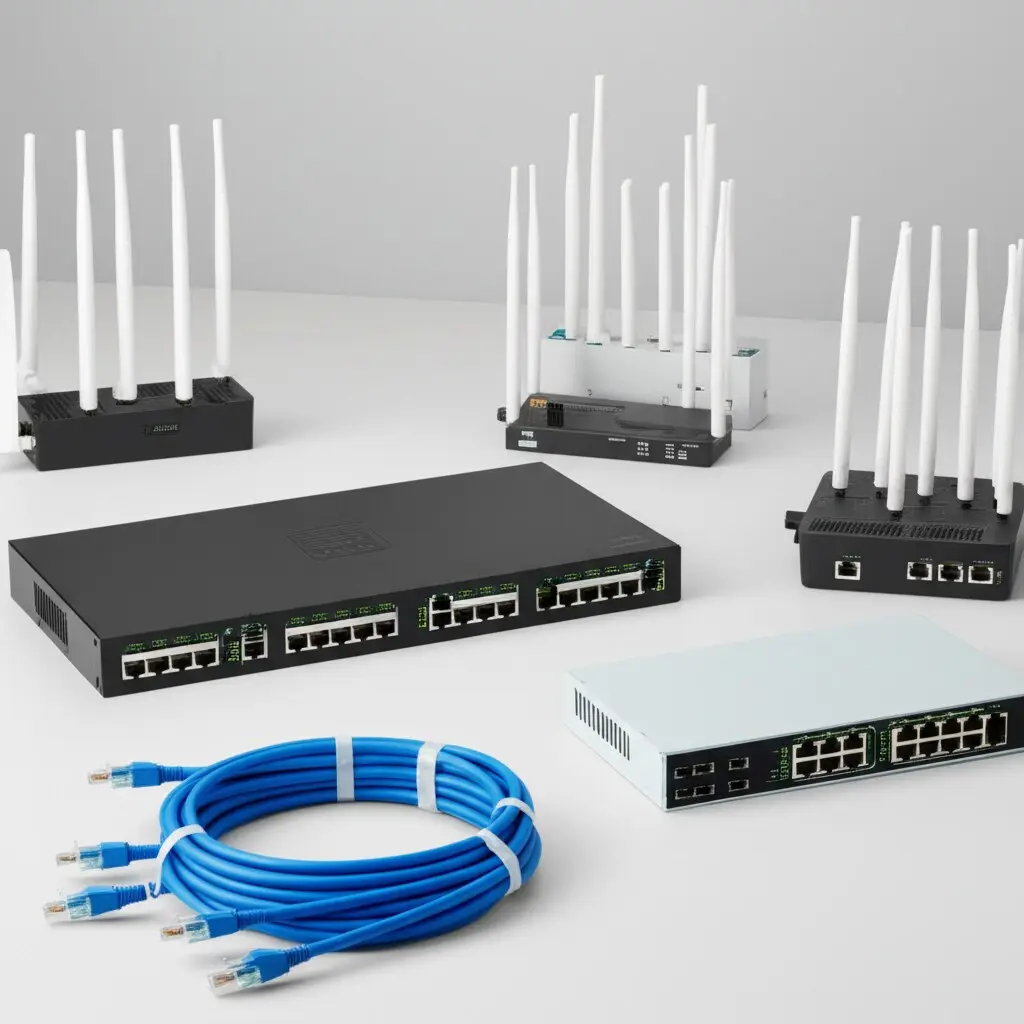
Equipment selected after diagnosis
Platform and model choices follow the requirement, existing estate, lifecycle and management approach.
Evidence base
Technical references used for this guide
- WLAN site survey guidelines
Cisco
Used for the distinctions between predictive, passive and active surveys, the role of RF assessment before deployment, and post-installation validation.
- Wireless site survey FAQ
Cisco
Used to frame survey preparation, environment-specific design targets and the need to consider client devices and applications.
- WiFi survey service overview
TP-Link Malaysia
Used as a current Malaysian market reference for RF audits, enhancement reports, indoor and outdoor requirements, and failover discussions.
FAQ
Questions Malaysian organisations ask before improving WiFi
Straight answers about scope, evidence, disruption and long-term operation.
What is a WiFi site survey?
A business WiFi site survey is a structured assessment of the premises, requirements, radio environment and supporting network. Depending on scope, it may include predictive planning, passive observations, active client tests, equipment and cabling review, findings, recommended changes and post-installation validation.
What is the difference between a predictive and an on-site survey?
A predictive survey models expected behaviour from plans and assumptions before installation. An on-site survey observes the real environment and, where scoped, the live network. Predictive work helps with early design; on-site evidence reveals materials, interference, mounting and operational conditions that drawings may not capture.
What does a WiFi heatmap show?
A heatmap visualises a selected metric across measured or modelled locations, such as observed signal or another survey value. Its meaning depends on the method, adapter, sampling path, floor plan and thresholds. It should be read with the test context and not treated as proof of capacity by itself.
Why is WiFi slow even when a device shows full signal bars?
Signal bars do not show available airtime, interference, client capability, switch or gateway congestion, internet performance or application response. A strong radio relationship can coexist with a busy channel, constrained uplink or slow external service, so the end-to-end path needs to be isolated.
Can Translife assess equipment installed by another company?
An existing estate can be assessed regardless of who installed it, subject to physical access, administrator credentials, platform support and an agreed scope. The findings can identify reusable equipment, unsupported components, configuration risks and dependencies that require access from the customer or incumbent provider.
Do I need to provide floor plans?
Accurate plans make preparation and location records easier, but their absence does not automatically prevent an assessment. For a larger or complex premises, plans, reflected ceiling information and room-use details materially improve design accuracy. Any plan limitations or measurements created on site should be documented.
How long does a business WiFi assessment take?
Duration depends on floor area, number of floors and buildings, access restrictions, network complexity, survey method, operating conditions and reporting depth. A walkthrough of a small office is different from active testing across an occupied hotel or warehouse, so timing is quoted after discovery.
Can the network improve without replacing every access point?
Often, yes. Evidence may support configuration changes, cable repair, access-point relocation, selective additions, switch or PoE remediation, traffic separation or internet changes. Full replacement is justified when the current platform is unsuitable, unsupported, unreliable or cannot meet the agreed requirement.
What can be included in the survey report?
A quoted report can include the requirement summary, scope map, existing topology and inventory, test method, observed findings, coverage visuals where measured, interference or capacity observations, remediation priorities, equipment and cabling dependencies, assumptions, exclusions and a validation plan.
How is the network verified after an upgrade?
Validation repeats agreed checks at representative locations, paths, devices and load conditions. It can cover connection, permitted service access, measured radio or active-test results, roaming observations and segmentation checks. Exceptions and client-specific limitations should be recorded rather than hidden by a blanket coverage claim.
Explore more
Continue planning your connectivity project
Use the service page that matches the next decision in your network plan.
Testimonials
What Our Clients Say
Trusted by corporations, SMEs, and government agencies in Malaysia and Singapore.
“Great suggestion of the output format of translation which I never thought of. It helps our people at site understand the translation much easier.”
DHL Malaysia
Plan with evidence
Request a WiFi assessment for your premises
Tell us what users experience, where it happens, which devices and applications matter, when the site is busiest, and what network equipment is already installed. We will use that context to define an appropriate assessment scope.
Prefer to provide drawings first? Use the contact page and describe the premises, operating hours, known dead zones and approximate user or device count.