
Property-wide connectivity with clear boundaries
Commercial Building &
Multi-Tenant WiFi Malaysia
Plan owner, tenant and carrier responsibilities across entrances, telecommunications rooms, risers, floors, common areas and managed tenant services without turning the property into one flat network.
Mon–Fri 9–6 GMT+8 · MY: +60384081397 · SG: +6586605216
Direct answer
A multi-tenant building network should define ownership and service demarcation before it defines WiFi names or access-point counts.
Commercial property connectivity can include carrier entrances, telecommunications rooms, fibre risers, floor distribution, landlord systems, common-area WiFi, coworking users and tenant-specific networks. The design must state which infrastructure belongs to the owner or management body, which service belongs to each carrier or tenant, how tenants are isolated, who may administer shared equipment, how personal data is handled and what happens when a tenant moves. Internet resale, carrier service and regulatory obligations require separate commercial and professional confirmation; installing a managed network does not grant those rights automatically.
Technical review
Translife connectivity team
Updated
- Office towers, mixed commercial properties, coworking centres, malls and managed business premises
- Carrier, property, operator and tenant handoffs mapped at rooms, risers, panels and gateways
- Common-area, management, building-system, guest and tenant traffic separated by approved policy
- New-build, brownfield retrofit, landlord-network upgrade and tenant onboarding or exit workflows
100+
Languages
10,000+
Clients Served
21+
Years Experience
PM-led
Project-Managed
Selected clients in Malaysia
Search by symptom
The network problems this service addresses
Start with the operational symptom, then measure the radio, cabling and traffic conditions that can produce it.
Every tenant assumes the landlord owns the fault
A failure can sit with the carrier, building backbone, shared gateway, tenant equipment or application. A documented demarcation and test point prevents circular escalation.
Shared WiFi exposes other occupants
Different network names or passwords do not prove tenant isolation. Switching, routing, firewall, management and representative blocked-path tests must express the boundary.
The fibre riser has no current records
Unlabelled cores, panels and floor cabinets make onboarding slow and dangerous. Route, assignment, loss evidence and ownership should follow each tenant service.
Common areas work but tenant suites do not
Lobby coverage does not prove service behind tenant walls, meeting rooms or fitted ceilings. The property baseline and tenant fit-out responsibilities need separate acceptance zones.
A departing tenant leaves accounts and patching behind
Licences, portal users, credentials, switch ports and circuits can remain active after occupancy ends. Offboarding must revoke access and update physical and logical records.
The shared internet model was never approved
Provider terms, licensing, billing, acceptable use, privacy and support responsibilities can differ from an ordinary customer connection. The owner must confirm the intended operating model before it is marketed.
Diagram 1
Commercial building path from carrier entrance to tenant service
This conceptual topology keeps provider, property and tenant layers visible. Final ownership and access follow the building agreements, technical codes and approved service model.
- 1
Carrier entrance
One or more providers reach an agreed building demarcation through approved external infrastructure.
- 2
Building handoff
Main telecommunications space, panels and owner-controlled infrastructure establish the property boundary.
- 3
Riser & floor
Documented fibre, pathways and distribution connect approved floor or zone endpoints.
- 4
Service boundary
Landlord, common-area, coworking or tenant gateways and policies separate operational responsibility.
- 5
Occupant network
Tenant and shared users receive only the connectivity and resources assigned to their service.
Diagram 2
Tenant experience depends on five ownership layers
The same outage message can originate with a tenant device, local suite, shared property network, riser or carrier. Each layer needs an evidence point and escalation owner.
Tenant endpoint
User device, tenant identity, local application and any tenant-owned router, switch or access point.
Suite or shared access
Tenant outlets, access points, coworking service, meeting rooms and floor distribution.
Property policy
Shared gateways, segmentation, common-area services, building systems and management access.
Building backbone
Telecommunications rooms, risers, fibre, panels, power, cabinets and physical access.
Carrier & external
Provider handoff, commercial service, upstream routing, external applications and provider support.
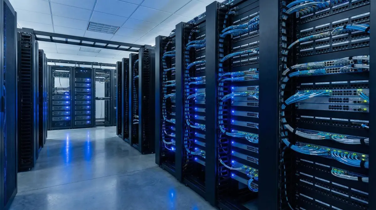
Name every responsibility
Developer, owner, management, operator, carrier and tenant boundaries
A building network spans organisations with different contracts, access rights and technical responsibilities, so ownership must be visible at each handoff.
The stakeholder workshop identifies the developer or owner, management corporation or appointed property manager, facilities team, coworking or managed-service operator, carriers, network support provider, building-system vendors and tenants. It records who provides entrances, ducts, rooms, risers, panels, power, active equipment, internet, WiFi, credentials, support and billing. A physical asset can be owner-controlled while the service crossing it belongs to a provider or tenant. Those distinctions appear in the topology and operating procedure.
Malaysian Technical Standards Forum Berhad lists current registered codes for fixed-network facilities, including G024:2024 for in-building and external infrastructure and G055:2025 for brownfield facilities. Its fixed-network working group describes these codes as covering associated infrastructure and cabling while supporting end-user needs and minimising deployment and maintenance disruption. Project designers determine applicability and contractual requirements; this page does not declare every property automatically compliant.
Demarcation points include the private-property or building entrance, main telecommunications room, provider termination, owner panel, floor cabinet, tenant handoff and any shared managed gateway. Each point receives a test method and contact. If a tenant supplies its own firewall after the building handoff, the property may prove the delivered circuit while the tenant proves its local network. Where the property operates a complete managed service, those responsibilities and permitted access must be expanded explicitly.
- List the parties that own pathways, equipment, services, accounts, support and billing.
- Mark provider, property, shared-operator and tenant handoffs on the topology.
- Assign a test point and escalation contact to every operational boundary.
- Confirm applicable technical, contractual and regulatory duties with responsible advisers.
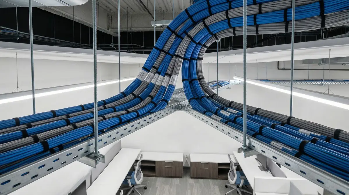
Match the property state
New development, brownfield retrofit, shared-service upgrade or tenant fit-out
The right project path depends on whether pathways are still being designed, the building is occupied or a tenant service must change without affecting neighbours.
A new development can coordinate provider access, ducts, main and floor telecommunications spaces, risers, fibre, equipment power, cooling or ventilation, common-area access points and tenant handoff locations before finishes close. Space and pathway reservations support future carriers and occupancy changes, but final services still require provider engagement and commissioning. Architect, electrical, mechanical, fire, security, lift, building-management and tenant-fit-out responsibilities are written into the interface schedule.
A brownfield assessment begins with rooms, risers, panels, fibres, cabling, pathways, active equipment, accounts, providers and current tenant assignments. Access can be constrained by occupied suites, locked spaces and undocumented modifications. Useful infrastructure is retained when its condition, capacity, ownership and supportability are proven. The new MTSFB G055:2025 brownfield code provides current Malaysian context for fixed-network facilities in existing properties; responsible project parties confirm how it applies to the actual site.
A shared-service upgrade or tenant fit-out requires change boundaries. The property baseline may deliver a tested circuit, internet service or managed WiFi to an agreed point, while tenant contractors build inside the suite. Work windows, ceiling permissions, riser access, patching and provider coordination follow building rules. A pilot floor or limited common area can validate the service and support model before a broad occupied-building migration. Existing tenants are not moved silently because a new standard is preferred.
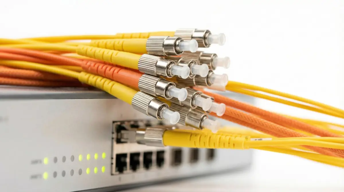
Build the shared physical layer
Telecommunications rooms, fibre risers, floor cabinets and pathways
The property backbone should make tenant services traceable while preserving access, capacity and future changes for the building owner.
The physical design maps provider entrance facilities, main and floor rooms, vertical and horizontal pathways, fibre and copper distribution, cabinets, panels, power and access. Fibre can support floor or building distribution where distance, capacity and interfaces justify it, while suitable copper serves nearby endpoints within its design. Core counts and pathway capacity account for current assignments, useful spares, new tenants and restoration strategy. Additional fibres in one riser do not create a physically diverse route.
Rooms and cabinets need controlled access, labels, lighting, suitable environment, power and working clearances. They should not become general storage or contain undocumented tenant devices. Provider and tenant access is scheduled and supervised according to property policy. Electrical, fire-stopping, civil, structural and cooling work remains with qualified parties. The building network proposal does not claim ownership of shared facilities that the property or carrier has not authorised it to change.
Fibre and cable records identify route, panel, core or port, source, destination, tenant or service, state and test evidence. New or changed fibres receive loss results appropriate to the cable plant. Floor and tenant handoff labels match both ends and the management register. Temporary services, damaged spares and inaccessible pathways remain visible. This allows a future tenant move to use known capacity instead of tracing live building circuits by trial and error.
- Map entrances, main and floor rooms, risers, pathways, panels, power and access ownership.
- Reserve capacity by realistic occupancy and service scenarios, not empty conduit appearance.
- Keep qualified electrical, fire, structural, civil and environmental work explicit.
- Connect every core or port assignment to tenant, service, state and test evidence.
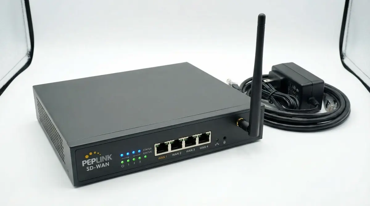
Choose what the property supplies
Carrier-only handoff, managed circuit, shared internet or full managed WiFi
Different commercial models create different technical, support, billing, privacy and regulatory responsibilities.
In a carrier-only model, the property mainly provides approved access and passive infrastructure while each tenant contracts with its provider. In a managed-circuit model, the building or operator may deliver a defined Ethernet or internet handoff and the tenant manages its suite. Coworking and serviced-office models may provide full wired and wireless access, identity and support. Common-area WiFi can remain a separate property service for lobby, meeting, event or visitor zones.
Before offering shared internet or managed tenant access, the owner or operator confirms provider terms, licensing or regulatory implications, charging, acceptable use, support, content and incident responsibilities with appropriate advisers. An ordinary business broadband contract is not assumed to permit resale or redistribution. Translife can design and implement the approved technical model; it does not grant carrier rights, make billing lawful or replace MCMC, legal, tax or commercial guidance.
The service description states the handoff, included bandwidth or policy where applicable, authentication, public addressing, permitted equipment, support hours, planned maintenance, provider dependencies and tenant responsibilities. Performance is not guaranteed by access-point count or a shared headline speed. The operator needs a capacity and fair-use method, a way to observe service boundaries and an escalation path for tenant, property and carrier faults. Custom tenant requirements are quoted separately rather than weakening every tenant’s baseline.
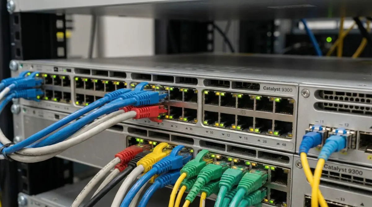
Isolate by approved need
Tenant, landlord, building-system, guest and management networks
Multi-tenancy requires policy at wireless, wired, routing, firewall and administrator layers; a separate password is not sufficient isolation.
Tenant groups can receive distinct wireless or wired assignments with routing and firewall policy that permits only approved destinations. Landlord administration, property staff, CCTV, access control, building management, digital signage, public guest service and network management may use separate service groups. The exact architecture follows system ownership and risk. A VLAN is an implementation mechanism, not evidence by itself; representative prohibited paths are tested through the actual gateway and switch configuration.
Administrator boundaries are also separated. A property operator may manage shared infrastructure without viewing tenant application traffic, while a tenant may manage its own firewall after the handoff. Role-based access, protected management paths, logging and configuration records are used where the platform supports them. CISA recommends current device inventories, trusted management paths, central configuration storage and monitoring of unauthorised changes. Those practices inform the shared platform but do not certify the building against a security standard.
Tenant-specific exceptions need an owner and expiry or review condition. A legacy printer, discovery protocol, public service or vendor-managed device may require limited communication. The solution documents the exact path instead of opening unrestricted tenant-to-tenant or tenant-to-management access. Security testing stays within written authorisation and avoids tenant data. High-assurance penetration testing or formal compliance assessment is a separate specialist engagement.
- Define communication required by each tenant, property and building-system group.
- Apply the boundary consistently across SSIDs, switch ports, routing, firewall and management.
- Restrict shared-platform administration and monitor configuration changes where supported.
- Test representative allowed and blocked paths without inspecting tenant content.
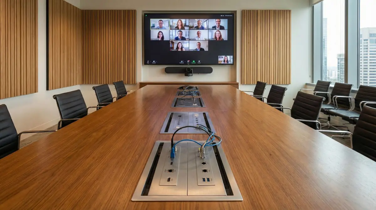
Operate shared spaces responsibly
Lobby, meeting-room, coworking, visitor and event WiFi
Common-area WiFi needs its own coverage, capacity, access, privacy and support promise rather than borrowing a tenant network.
The property maps lobbies, lounges, meeting suites, shared desks, retail areas, amenities, outdoor zones and temporary event spaces. Each zone has ordinary and peak occupancy, expected applications, staff devices and service hours. A shared meeting floor may need more concurrent capacity than a corridor, while walls and tenant fit-outs change coverage. The permanent network supports its agreed baseline; large conferences or productions may require dedicated Event WiFi and additional internet capacity.
Access can use accepted terms, vouchers, identity, room or booking integration where the selected platform and confirmed systems support it. Integration is not assumed. If the operator collects names, email addresses, phone numbers, company, device information or marketing choices, it decides purpose, notice, retention, disclosure, security and rights handling. The Personal Data Protection Commissioner’s privacy-notice guide provides current Malaysian guidance on what a notice should communicate. Technical portal setup does not create automatic PDPA compliance.
Guest and coworking policy can set reasonable bandwidth, session and local-access controls while protecting property and tenant services. The operator needs a help path for failed login and an incident process that does not expose other occupants’ information. Portal logs and network telemetry are accessed only by authorised roles and retained according to approved policy. Client isolation and firewalls reduce unnecessary local access but do not protect every personal device from malicious internet content or cellular activity.
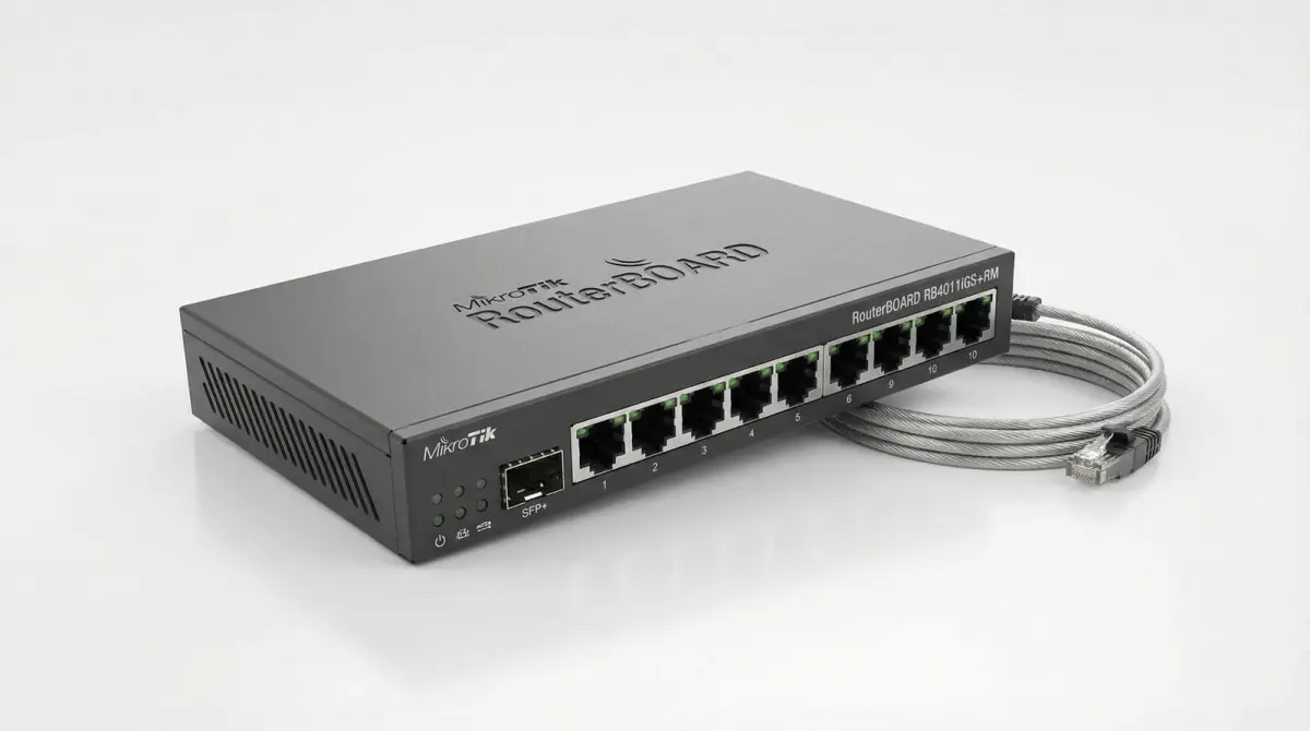
Design failure boundaries
Multiple carriers, shared gateways, route diversity and support escalation
Resilience is credible only when provider, pathway, power, gateway and support dependencies are examined separately.
A building may accommodate several carriers for tenant choice, use multiple links for a shared service or deliver a single provider handoff. The design records provider entry paths, demarcation, equipment, power, commercial ownership and support contacts. Two carriers can still share ducts, exchanges or building rooms, so independence is confirmed rather than inferred from different logos. Provider activation schedules and permissions remain subject to the carriers and property.
Shared-service resilience can include a second internet path, compatible gateway policy, selected UPS coverage, spare fibre cores, redundant switching or alternate physical routes. Each measure protects a named failure. A second provider does not protect a failed shared gateway, and dual gateways do not protect one unpowered room. Failover capacity and address changes can affect tenant VPNs, voice or cloud sessions. Approved tests record which services continued and which required reconnection without promising universal seamlessness.
Fault triage identifies the tenant endpoint, suite network, property distribution, shared gateway, building backbone and provider boundary. Monitoring and test points supply evidence to the responsible party. Support hours and response ownership are explicit for the property and each tenant service. If a carrier outage occurs, the operator raises the provider case and validates the customer-side path; it cannot replace the carrier’s restoration commitment. Incident summaries avoid exposing one tenant’s network details to another.
- Record provider entrance, demarcation, equipment, power, contract and escalation ownership.
- Check physical and upstream independence before calling links or routes diverse.
- Tie gateways, UPS, fibres and failover policy to specific failure scenarios.
- Separate tenant, property and carrier evidence during incident escalation.
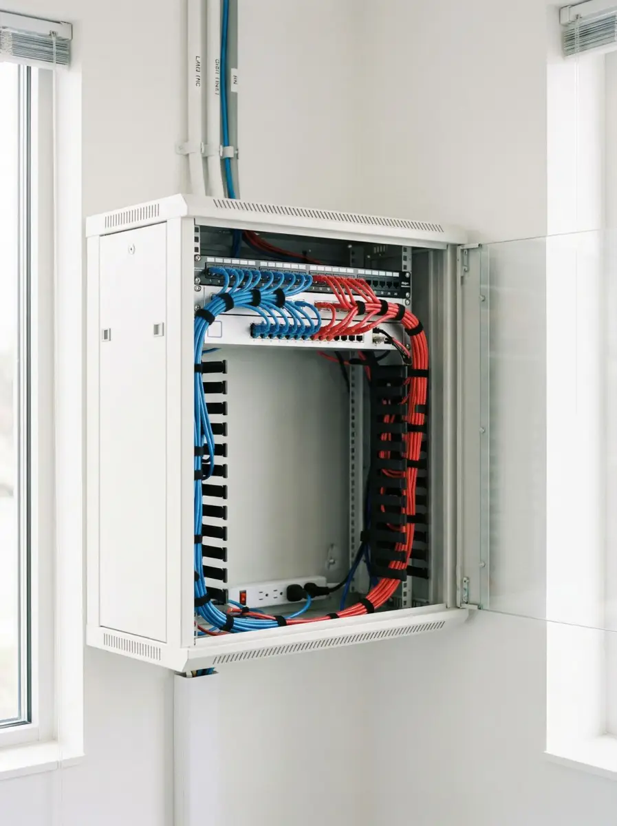
Support occupancy change
Tenant onboarding, moves, expansion, offboarding and handover
The network operating model should make an occupancy change routine without leaving active accounts, unknown circuits or another tenant’s configuration behind.
Onboarding records the tenant’s suite, contacts, approved service model, required date, provider, handoff, addressing or identity needs, access rules, special systems and fit-out contractor. The property reserves and tests the assigned riser cores, ports or managed network before occupancy. Tenant equipment and support responsibility begin at the agreed boundary. Any custom firewall rules, public services, VPNs or additional access points receive separate review so they do not compromise the shared baseline.
Moves and expansions update physical and logical assignments together. New outlets, access points or capacity are surveyed rather than assumed from the previous suite. Change windows consider neighbouring tenants and shared equipment. Temporary swing services are labelled with expiry and owner. The operator retains configuration backups and approval records, and significant changes are validated with the tenant workflow. Tenant confidential details are not copied into general building documentation beyond what operations require.
Offboarding confirms the end date, revokes identities and administrative roles, removes or reassigns portal access, closes public rules, releases addresses, disconnects approved ports and updates fibre and patch schedules. Tenant-owned equipment and data are returned or handled under the agreement; nothing is reset or disposed of without authority. Final handover gives the property current topology, assignments, test evidence, accounts, licences, provider contacts, exceptions and capacity status, ready for the next occupancy cycle.
- Create a tenant service record with handoff, contacts, access, provider and custom requirements.
- Update fibre, ports, policy and documentation together during moves and expansion.
- Give temporary services an owner, identifier and expiry or review condition.
- Revoke access and release assignments systematically at tenant exit.
Decision guide
Choose the building service model before the equipment
These models create different owner, tenant, carrier and support duties. Final architecture follows property agreements, approved regulatory guidance and site evidence.
| Property service model | Questions to answer | Design focus |
|---|---|---|
| Carrier access only | Which providers may enter, where is demarcation, and what rooms, risers and tenant pathways does the property supply? | Neutral documented infrastructure, controlled provider access, labelled handoffs and carrier-versus-property ownership. |
| Managed tenant circuit | What is delivered at the handoff, who manages the gateway, and what performance, support and permitted equipment apply? | Testable circuit boundary, tenant isolation, monitoring, service description and escalation between operator and tenant. |
| Shared internet service | Do provider terms and applicable rules permit the model, and how are capacity, billing, privacy and support managed? | Approved commercial model, fair-use and capacity policy, shared-edge resilience, tenant separation and incident process. |
| Coworking or serviced office | How are members and guests identified, which shared resources are allowed, and how are joins, moves and exits handled? | Identity lifecycle, role-based access, room capacity, portal privacy, operator support and rapid tenant lifecycle controls. |
| Common-area WiFi only | Which lobby, amenity, meeting or event zones are included, and what data, capacity and service promise apply? | Zone survey, controlled guest access, property separation, approved privacy notice and event-capacity trigger. |
Delivery process
A commercial building network delivery sequence
The sequence begins with service and ownership because those choices determine rooms, risers, platforms, policy and long-term operations.
- 01
Stakeholder and service discovery
Identify owner, management, operator, carriers, tenants, facilities, systems, commercial model, regulations and operating responsibilities.
- 02
Building infrastructure audit
Review entrances, rooms, risers, pathways, fibre, panels, cabinets, power, environment, accounts, tenant assignments and capacity.
- 03
Demarcation and policy design
Define carrier, property and tenant handoffs, service groups, management roles, common areas, resilience and acceptance evidence.
- 04
Property and tenant phasing
Coordinate providers, fit-outs, occupied floors, access, qualified trades, communications, configuration backups, cutovers and rollback.
- 05
Boundary validation
Test building links, tenant and common-area workflows, permitted access, representative blocked paths and provider handoffs.
- 06
Operational handover
Transfer topology, riser and tenant assignments, results, accounts, provider contacts, privacy ownership, exceptions and lifecycle procedures.
Visual field guide
What the physical network work looks like
These illustrative installation views show the components and workmanship discussed on this page; final equipment and routes depend on the survey.
Building service handoff
Carrier, property and tenant infrastructure meet at owned and labelled boundaries.
Riser and floor backbone
Fibre routes, cores, panels and test records follow every assigned service.
Tenant service policy
Physical assignments and logical separation must express the same approved boundary.
Shared meeting spaces
Common areas have separate capacity, access, privacy and support requirements.
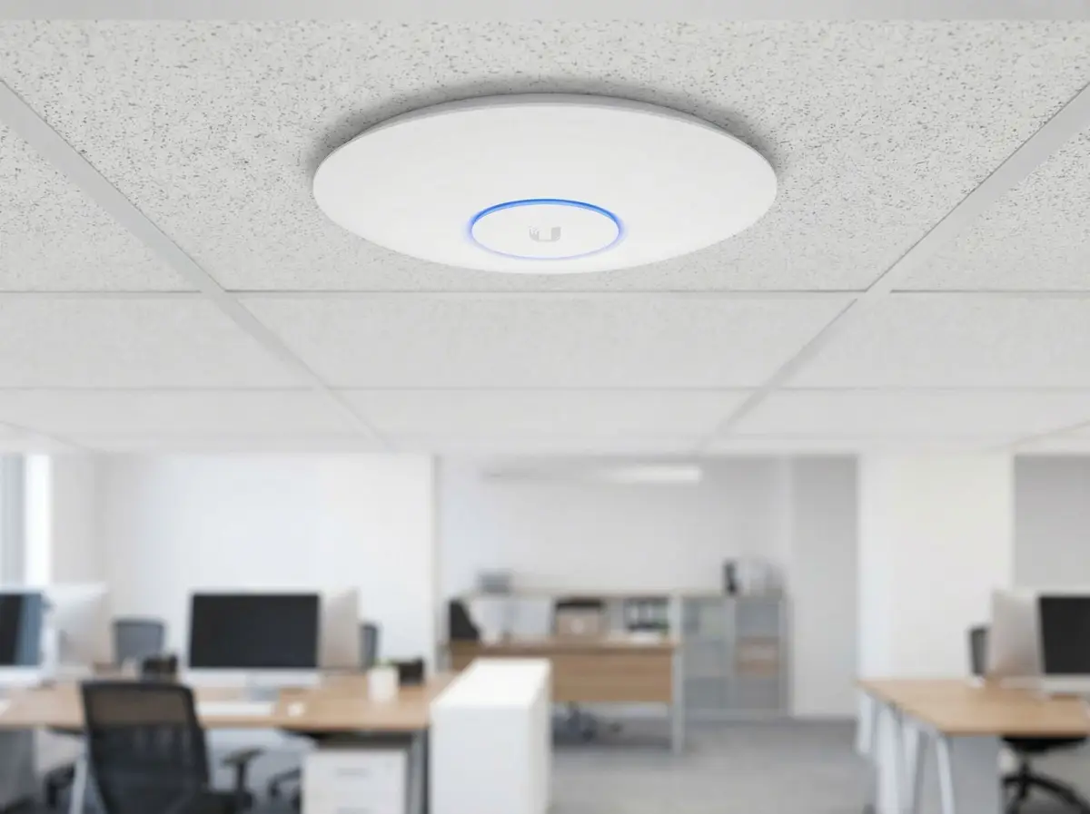
Property WiFi baseline
Access-point placement follows actual zones, tenant fit-outs and expected occupancy.
Floor distribution ownership
Controlled access, labels and assignment records keep tenant changes supportable.
Evidence base
Technical references used for this guide
- Registered Malaysian fixed-network technical codes
Malaysian Technical Standards Forum Berhad
Used for the current G024:2024 in-building and external and G055:2025 brownfield fixed-network technical-code context and the distinction between technical codes and mandatory standards.
- Fixed Network Facilities Working Group
Malaysian Technical Standards Forum Berhad
Used for the Malaysian scope of in-building and external infrastructure and cabling and the objective of supporting end users while minimising deployment and maintenance disruption.
- A Quick Guide to Privacy Notice
Personal Data Protection Commissioner Malaysia
Used to frame the operator’s notice responsibilities when common-area, coworking or visitor access collects personal information or marketing choices.
FAQ
Questions Malaysian organisations ask before improving WiFi
Straight answers about scope, evidence, disruption and long-term operation.
Who owns the network in a multi-tenant commercial building?
Ownership can be divided among carrier, developer, property owner or management body, shared-service operator and tenant. The topology and agreements should identify rooms, pathways, panels, fibre, active equipment, internet, accounts, support and billing at every handoff.
Can every tenant use one shared WiFi network?
They should not share unrestricted access by convenience. A managed model can assign controlled tenant, guest, property and building-system groups across wireless, switches, routing, firewall and management. Required and representative blocked paths should be tested.
Can a landlord resell one internet connection to tenants?
That must be confirmed against provider terms, the commercial arrangement and applicable licensing, regulatory, billing, tax, privacy and consumer obligations. Network installation does not grant resale rights. The owner or operator should obtain appropriate provider and professional guidance first.
How should carriers enter a commercial building?
Provider access, external infrastructure, building entrance, telecommunications room, demarcation and riser use should follow the approved property design, current applicable technical requirements and carrier agreement. Access, power, pathway and ownership are recorded before installation.
Can existing building fibre be reused for a new tenant?
Potentially, after route, endpoints, fibre type, connectors, core assignment, ownership and condition are confirmed and tested. Previous labels or link lights are not sufficient evidence. The tenant assignment and results should be updated at both ends.
What is the difference between landlord WiFi and tenant WiFi?
Landlord WiFi usually serves common areas, management or an approved shared service, while tenant WiFi serves the tenant’s suite and users. Ownership, identity, internet, security policy, support and acceptance boundaries should remain explicit even when one platform operates both.
How is WiFi planned for coworking and serviced offices?
The design maps rooms, desks, meeting areas, busy periods, member and guest identities, shared resources, tenant isolation, fair use, onboarding, offboarding, privacy, provider dependencies and support. Capacity and access policy are validated together.
Does separate VLAN configuration prove tenant isolation?
No. VLANs are one mechanism. Wireless assignments, switch ports, routing, firewall rules, shared services and administrator access must enforce the same boundary, and representative permitted and prohibited connections should be tested under written authorisation.
Can a commercial building have several internet providers?
Yes where property infrastructure, space, pathways, power, agreements and provider availability permit. Different providers are not automatically independent because they may share ducts, rooms or upstream facilities. Each handoff and support responsibility should be documented.
Does a guest WiFi portal make the building PDPA-compliant?
No. The operator remains responsible for lawful purpose, approved notice, collection, consent where applicable, disclosure, security, retention, rights and contact handling. Technical setup can implement the approved flow but cannot create automatic compliance.
What happens to network access when a tenant leaves?
Offboarding should revoke identities and administrator roles, close tenant-specific rules, release addressing, disconnect approved ports, update fibre and patch assignments and return or handle tenant equipment and data under authority. The property records the resulting capacity and exceptions.
What is needed for a multi-tenant WiFi quotation?
Useful inputs include building plans, occupancy and tenant model, owner and operator responsibilities, carriers, rooms and risers, fibre and cable records, common areas, current equipment, service and billing model, privacy flow, support hours, fit-out rules and expansion plans.
Explore more
Continue planning your connectivity project
Use the service page that matches the next decision in your network plan.
Testimonials
What Our Clients Say
Trusted by corporations, SMEs, and government agencies in Malaysia and Singapore.
“Great suggestion of the output format of translation which I never thought of. It helps our people at site understand the translation much easier.”
DHL Malaysia
Plan with evidence
Request a commercial building network assessment
Share the building plans, occupancy and tenant model, owner and operator responsibilities, carrier handoffs, rooms and risers, current fibre and equipment, common areas, proposed service and privacy model, fit-out rules and support expectations. We will use those inputs to define an appropriate assessment and delivery scope.
Prefer to provide drawings first? Use the contact page and describe the premises, operating hours, known dead zones and approximate user or device count.